Pins common to both z85x30 and z80x30, Figure – Zilog Z80230 User Manual
Page 20
SCC/ESCC
User Manual
UM010903-0515
General Description
13
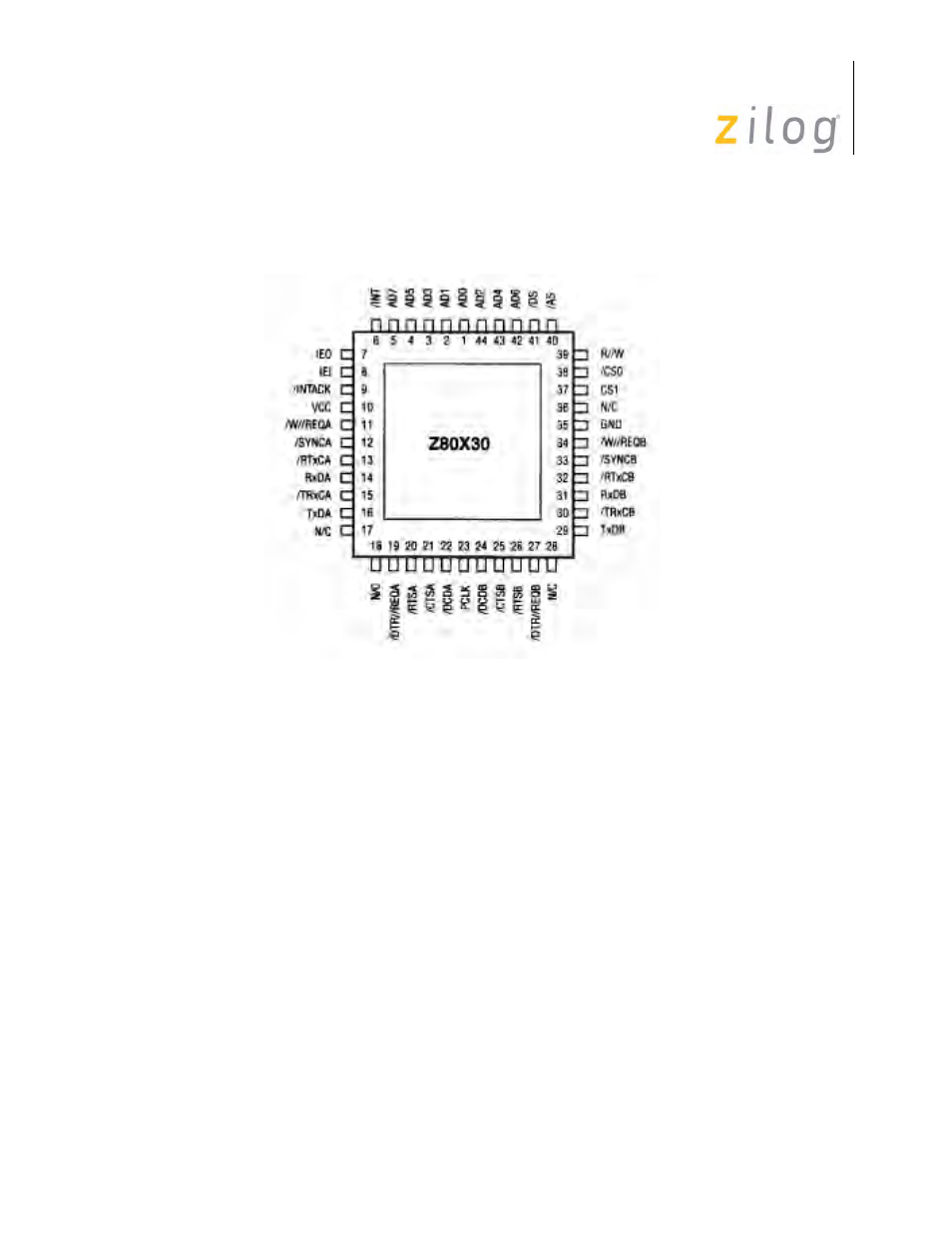
Z80X30 PLCC Pin Assignments
Pins Common to both Z85X30 and Z80X30
/CTSA, /CTSB.
Clear To Send (inputs, active Low). These pins function as transmitter enables if
they are programmed for Auto Enable (WR3, D5=1). A Low on the inputs enables the respective
transmitters. If not programmed as Auto Enable, they may be used as general-purpose inputs. Both
inputs are Schmitt-trigger buffered to accommodate slow rise-time inputs. The SCC detects pulses
on these inputs and can interrupt the CPU on both logic level transitions.
/DCDA, /DCDB
. Data Carrier Detect (inputs, active Low). These pins function as receiver
enables if they are programmed for Auto Enable (WR3, D5=1); otherwise, they are used as gen-
eral-purpose input pins. Both pins are Schmitt-trigger buffered to accommodate slow rise time sig-
nals. The SCC detects pulses on these pins and can interrupt the CPU on both logic level
transitions.
/RTSA, /RTSB.
Request To Send (outputs, active Low). The /RTS pins can be used as general-
purpose outputs or with the Auto Enable feature. When used with Auto Enable ON (WR3, D5=1)
in asynchronous mode, the /RTS pin goes High after the transmitter is empty. When Auto Enable
1