Zilog Z80230 User Manual
Page 129
SCC/ESCC
User Manual
UM010903-0515
Data Communication Modes
122
An additional bit carrying parity information is selected by setting bit D6 of WR4 to 1. This also
enables parity in the transmitter. The parity sense is selected by bit D1 of WR4. Parity is not nor-
mally used in SDLC mode.
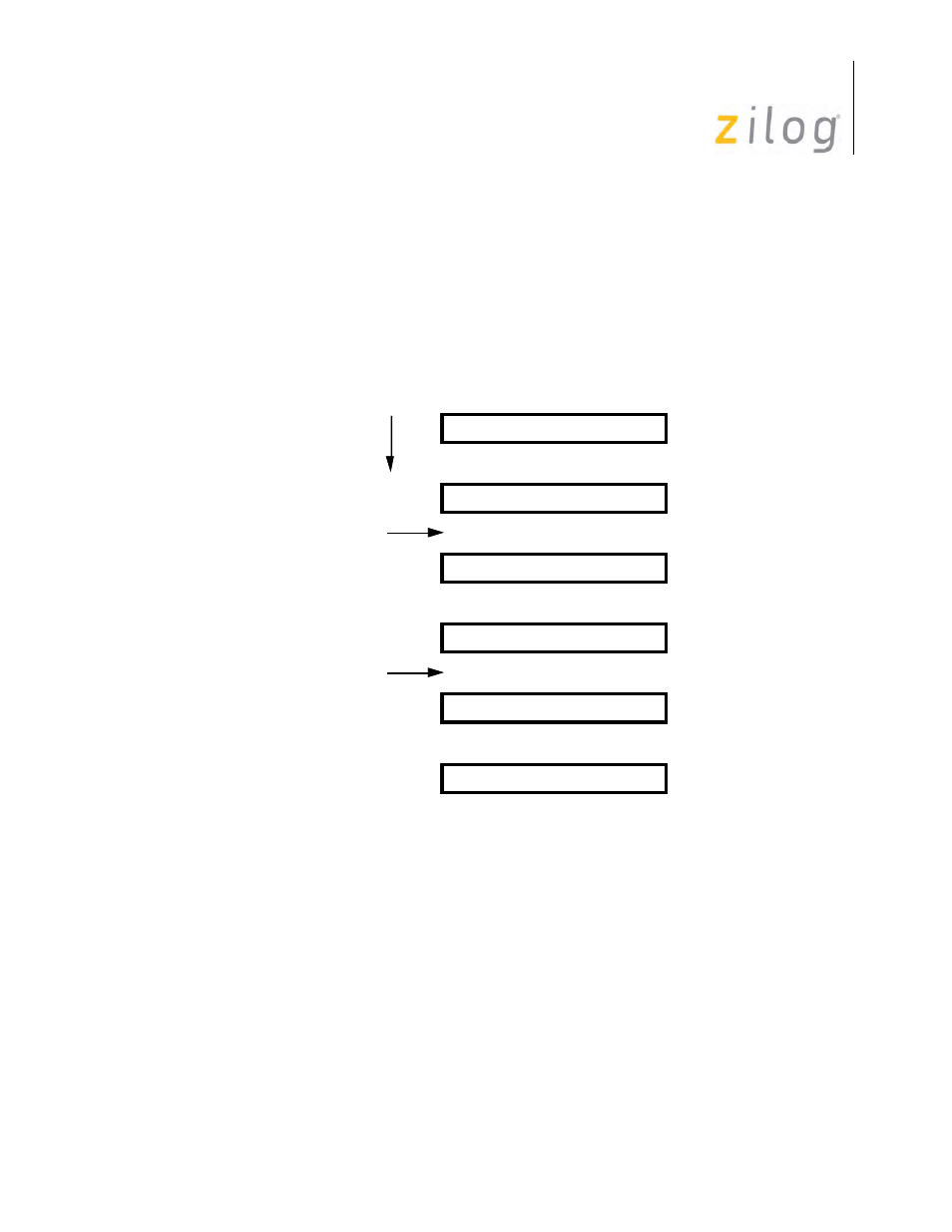
The character length can be changed at any time before the new number of bits have been assem-
bled by the receiver. Care should be exercised, however, as unexpected results may occur. A repre-
sentative example, switching from five bits to eight bits and back to five bits, is displayed in
Changing Character Length
Most bit-oriented protocols allow an arbitrary number of codes for the four different character
length options. The bits between opening and closing flags. The SCC allows valid data bits are
right-justified, meaning, if the number of for this by providing three bits of Residue Code in RR1.
valid bits given by the table is less than the character These indicate which bits in the last three
bytes transferred length, then the bits that are valid are the right-most or from the receive data
FIFO by the processor are actually least significant bits. It should also be noted that the Resivalid
data bits (and not part of the frame check sequence due Code is only valid at the time when the
End of Frame or CRC).
on page 123 gives the meanings of the different bit in RR1 is set to
1.
6 5 4 3 2 1
Receive Data Buffer
7
8
11 10 9 8 7 6
12
13
19 18 17 16 15 14
20
21
27 26 25 24 23 22
28
29
32 31 30 29 28 27
33
34
37 36 35 34 33 32
38
39
Time
Change from Five to Eight
Change from Eight to Five
5 Bits
5 Bits
5 Bits
8 Bits
8 Bits