Zilog Z80230 User Manual
Page 113
SCC/ESCC
User Manual
UM010903-0515
Data Communication Modes
106
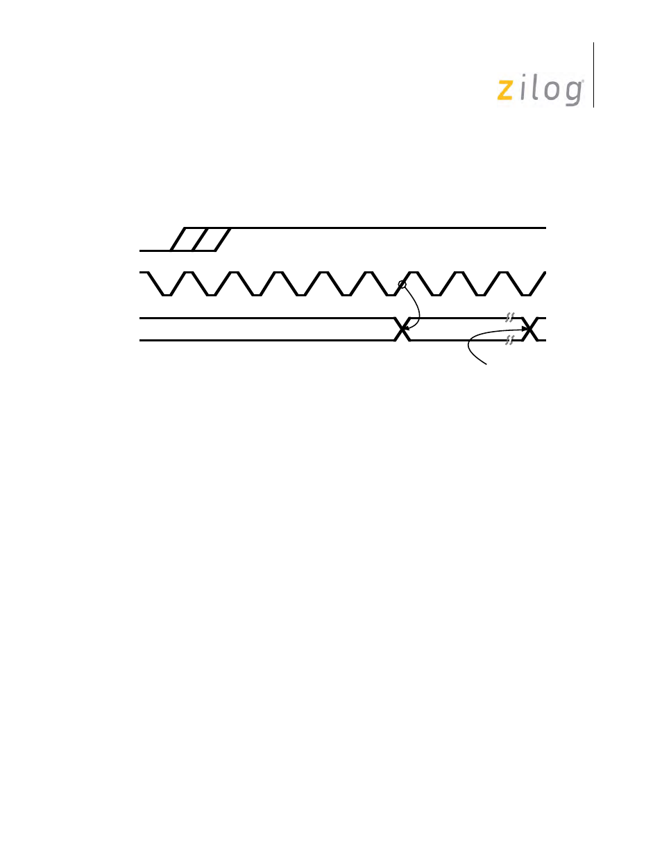
In all cases except External Sync mode, the /SYNC pin is an output that is driven Low by the SCC
to signal that a sync character has been received. The /SYNC pin is activated regardless of charac-
ter boundaries, so any external circuitry using it should only respond to the /SYNC pulse that
occurs while the receiver is in Hunt mode. The timing for the /SYNC signal is displayed in
/SYNC as an Output
To prevent sync characters from entering the receive data FIFO, set the Sync Character Load
Inhibit bit (D1) in WR3 to 1. While this bit is set to 1, characters about to be loaded into the
receive data FIFO are compared with the contents of WR6. If all eight bits match the character, it
is not loaded into the receive data FIFO. Because the comparison is across eight bits, this function
should only be used with 8bit sync characters. It cannot be used with 12- or 16-bit sync characters.
Both leading sync characters are removed in the case of a 6-bit sync character. Care must be exer-
cised in using this feature because sync characters which are not transferred to the receive data
FIFO will automatically be excluded from CRC calculation. This works properly only in the 8-bit
case.
The number of bits per character is controlled by bits D7 and D6 of WR3. Five, six, seven, or eight
bits per character may be selected via these two bits. The data is right-justified in the receive data
buffer. The SCC merely takes a snapshot of the receive data stream at the appropriate times, so the
“unused” bits in the receive buffer are only the bits following the character in the data stream.
An additional bit carrying parity information is selected by setting bit D0 of WR4 to 1. Note that
this also enables parity for the transmitter. The bit D1 of WR4 selects parity sense. If this bit is set
to 1, the received character is checked for even parity. If WR4 D1 is reset to 0, the received char-
acter is checked for odd parity. The additional bit per character is transferred to the FIFO as a part
of data when the data plus parity is less than 8 bits per character. The Parity Error bit in the receive
error FIFO may be programmed to cause a Special Receive Condition interrupt by setting bit D2
of WR1 to 1. Once set, this error bit is latched and remains active until an Error Reset command
has been issued. If interrupts are not used to transfer data, the Parity Error, CRC Error, and Over-
run Error bits in RR1 should be checked before the data is removed from the receive data FIFO.
State Changes in One
/RTxC Clock Cycle
/RTxC
PCLK
/SYNC