Zilog Z80230 User Manual
Page 80
SCC/ESCC
User Manual
UM010903-0515
SCC/ESCC Ancillary Support Circuitry
73
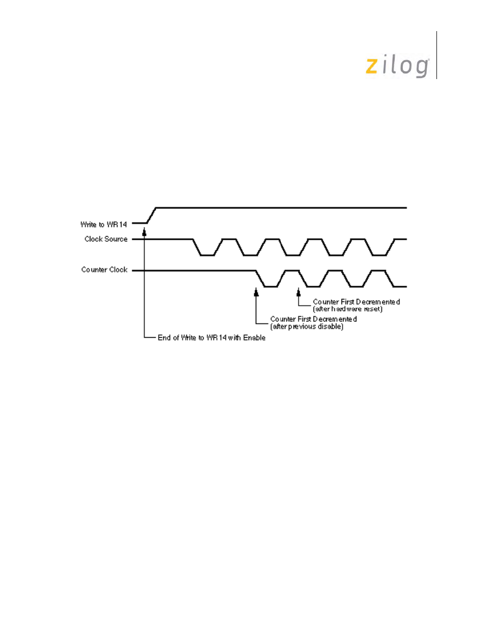
The BRG is enabled while bit D0 of WR14 is set to 1. It is disabled while WR14 D0=0 and after a
hardware reset (but not a software reset). To prevent metastable problems when the baud rate gen-
erator is first enabled, the enable bit is synchronized to the baud rate generator clock. This intro-
duces an additional delay when the baud rate generator is first enabled (
). The baud rate
generator is disabled immediately when bit D0 of WR14 is set to 0, because the delay is only nec-
essary on start-up. The baud rate generator is enabled and disabled on the fly, but this delay on
start-up must be taken into consideration.
Baud Rate Generator Start Up
The formulas relating the baud rate to the time-constant and vice versa are shown below.
In these formulas, the BRG clock frequency (PCLK or /RTxC) is in Hertz, the desired baud rate in
bits/sec, Clock Mode is 1 in sync modes, 1, 16, 32 or 64 in async mode and the time constant is
dimensionless. The example in
assumes a 2.4576 MHz clock (from /RTxC) factor of 16 and
shows the time constant for a number of popular baud rates.
For example:
Time Constant
Clock Frequency
2
Clock Mode
Baud Rate
-------------------------------------------------------------------------------- 2
–
=
Baud Rate
Clock Frequency
2
Clock Mode
Time Constant 2
+
----------------------------------------------------------------------------------------------------
=