Scc/escc user manual – Zilog Z80230 User Manual
Page 135
SCC/ESCC
User Manual
UM010903-0515
Data Communication Modes
128
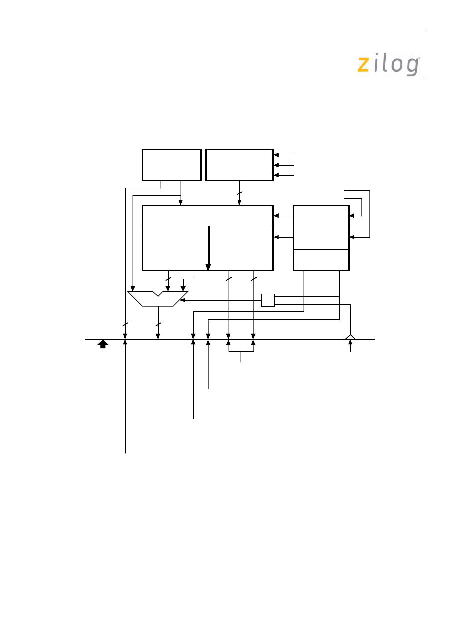
FIFO Detail.
For a better understanding of details of the FIFO operation, refer to the block dia-
SDLC Frame Status FIFO (N/A on NMOS)
Enable/Disable.
The frame status FIFO is enabled when WR15 bit D2 is set and the CMOS/
ESCC is in the SDLC/HDLC mode. Otherwise, the status register contents bypass the FIFO and
SCC Status Reg
Residue Bits(3)
Overrun, CRC Error
Byte Counter
Reset on Flag Detect
Increment on Byte DET
Enable Count in SDLC
RR1
14 Bits
5 Bits
FIFO Array
10 Deep by 19 Bits Wide
Head Pointer
4-Bit Counter
4-Bit Comparator
Over
Equal
5 Bits
EOF = 1
Tail Pointer
4-Bit Counter
End of Frame Signal
Status Read Comp
EN
6-Bit MUX
6 Bits
RR1
2 Bits
6 Bits
8 Bits
Frame Status FIFO Circuitr
In SDLC Mode the following definitions apply.
- All Sent bypasses MUX and equals contents of SCC Status Register.
- Parity Bits bypasses MUX and does the same.
- EOF is set to 1 whenever reading from the FIFO.
RR7 D5-D0 + RR6 D7 - D0
Byte Counter Contains 14 bits
for a 16 KByte maximum count.
RR7 D6
FIFO Data available status bit Status Bit set to 1
When reading from FIFO.
WR(15) Bit 2
Set Enables
Status FIFO
RR7 D7
FIFO Overflow Status Bit
MSB pf RR(7) is set on Status FIFO overflow
Interface
to SCC
FIFO Enable
RR6
Bits 5-0
Bit 6
Bit 7