Scc/escc user manual – Zilog Z80230 User Manual
Page 87
SCC/ESCC
User Manual
UM010903-0515
SCC/ESCC Ancillary Support Circuitry
80
the next 0 to 31 counting cycle, which effectively moves the edge of the clock that samples the
receive data closer to the center of the bit cell.
If the DPLL does not see any transition during a counting cycle, no adjustment is made in the fol-
lowing counting cycle.
If an adjustment to the counting cycle is necessary, the DPLL modifies count 5, either deleting it or
doubling it. Thus, only the Low time of the DPLL output is lengthened or shortened.
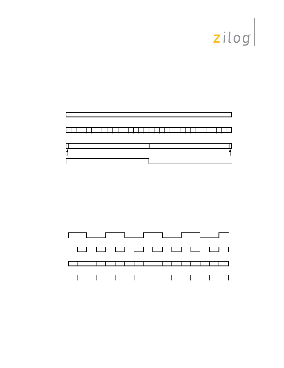
DPLL in NRZI Mode
While the DPLL is in search mode, the counter remains at count 16, where the DPLL outputs are
both High. The missing clock latches in the DPLL, which may be accessed in RR10, are not used
in NRZI mode. An example of the DPLL in operation is displayed in
DPLL Operating Example (NRZI Mode)
1
18 19 20
17
16
21 22 23 24 25 26 27 28 29 30 31
2 3 4 5
7 8 9
12 13 14
11
10
15
0
No Change
No Change
Bit Cell
Count
Correction
DPLL Out
Add One Count
Subtract One Count
6
Receive
Data
DPLL
Output
Correction
Windows
Count
Length
32 32 32 31 31 31 33 33 33
+1 -1 +1 -1 +1 -1 +1 -1 +1 -1 +1 -1 +1 -1 +1 -1 +1