Zilog Z80230 User Manual
Page 175
SCC/ESCC
User Manual
UM010903-0515
Register Descriptions
168
advisable to disable the baud rate generator while the new time constant is loaded into WR12 and
WR13. Ordinarily, this is done anyway to prevent a load of the down counter between the writing
of the upper and lower bytes of the time constant.
The formula for determining the appropriate time constant for a given baud is shown below, with
the desired rate in bits per second and the BR clock period in seconds. This formula is derived
because the counter decrements from N down to zero-plus-one-cycle for reloading the time con-
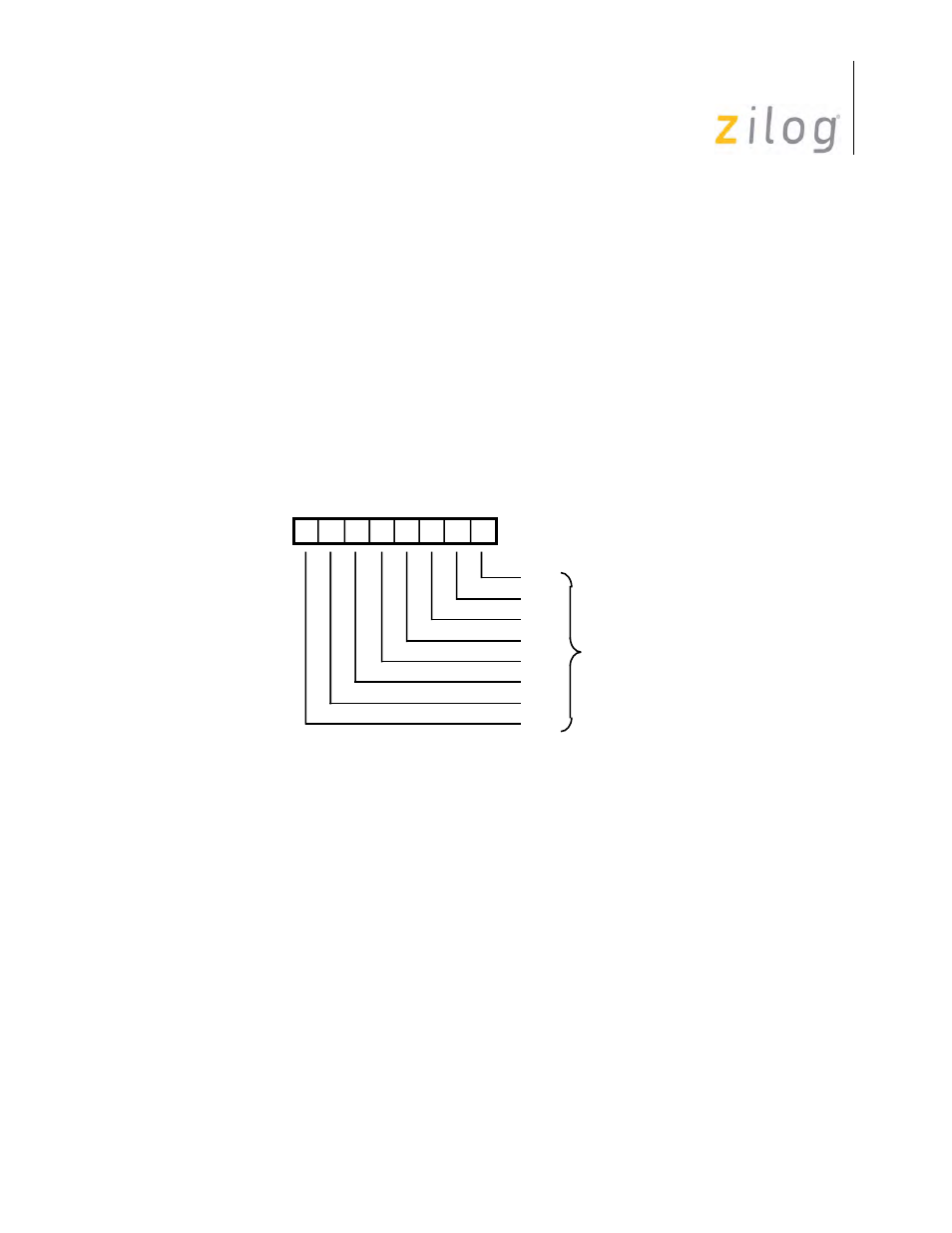
stant. This is then fed to a toggle flip-flop to make the output a square wave. Bit positions for
WR12 are displayed in
Write Register 12
Time Constant
Clock Frequency
2
Desired
R
ate
BR Clock Period
------------------------------------------------------------------------------------------------- 2
–
=
D7 D6 D5 D4 D3 D2 D1 D0
Write Register 12
TC0
TC1
TC2
TC3
TC4
TC5
TC6
TC7
Lower Byte of
Time Constant