Zilog Z80230 User Manual
Page 272
SCC/ESCC
User Manual
UM010903-0515
Application Notes
265
The ground pins are included as signal references with off-board hardware. When interconnecting
between two connectors among J5-J10, DO NOT jumper corresponding pins straight across, as
this connects outputs to outputs and inputs to inputs. Connect at least pin to the other pin 2, and
enough opposing inputs and outputs as needed to make the communications protocol meaningful.
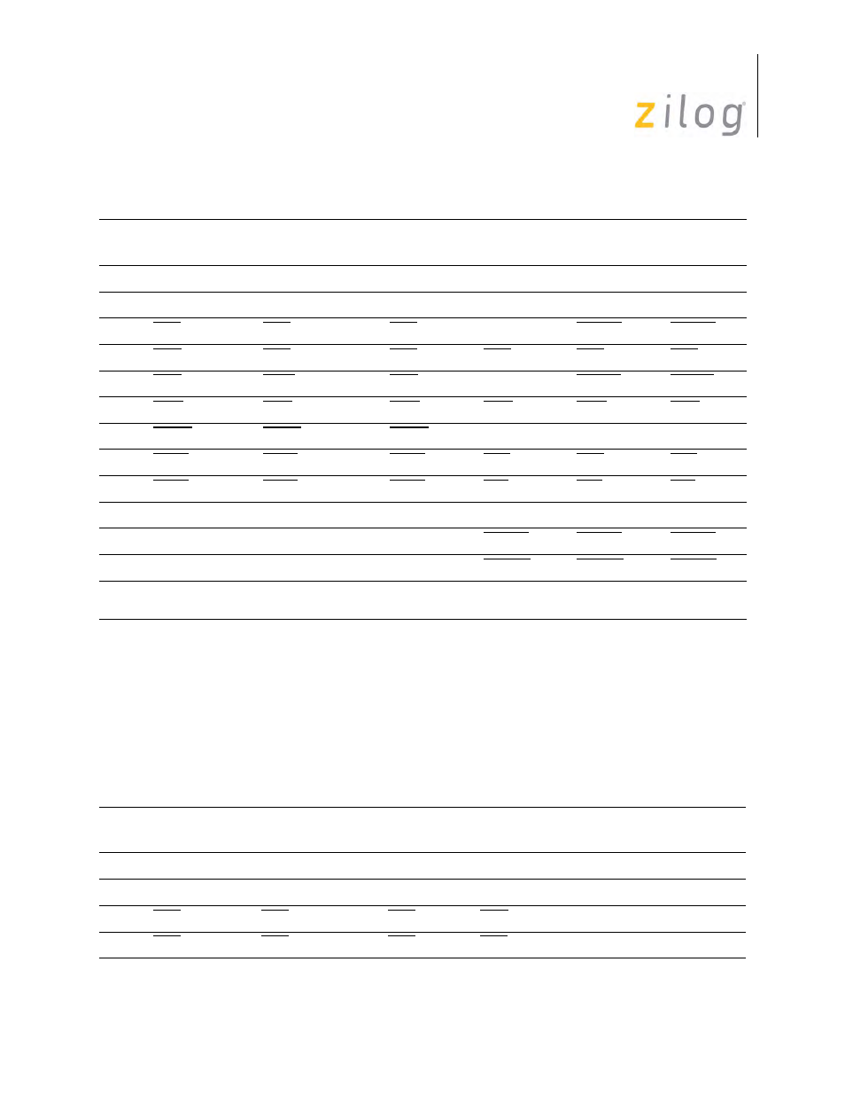
The pinout of the 12-pin J13-J15 connectors is similar to that of J5-J10, but more extensive. To
allow for the DCE connectors that were added in revision ‘B’ of the board, J13 and J14 are 16-pin
headers and J15 is a 14-pin header. See Table .
Pin Assignments of Standard Controller Connectors
Pins
J5 (E)SCC
A pin
J6 (E)SCC
B pin
J7, J8 ISCC
pin
J9 IUSC
pin
J10 MUSC or
USC A pin
J12 USC
B pin
1
TxD
TxD
TxD
TxD
TxD
TxD
2
RxD
RxD
RxD
RxD
RxD
RxD
3
RTS
RTS
RTS
(N/C)
RxACK
RxACK
4
CTS
CTS
CTS
CTS
CTS
CTS
5
DTR
DTR or N/C
(Note)
DTR
(N/C)
TxACK
TxACK
6
DCD
DCD
DCD
DCD
DCD
DCD
7
SYNC
SYNC
SYNC
(SYSCLK)
(SYSCLK)
(SYSCLK)
8
RTxC
RTxC
RTxC
RxC
RxC
RxC
9
TRxC
TRxC
TRxC
TxC
TxC
TxC
10
GND
GND
GND
GND
GND
GND
11
NA
NA
NA
TxREQ
TxREQ
TxREQ
12
NA
NA
NA
RxREQ
RxREQ
RxREQ
Note:
Controlled by the J24 jumper block. Must be N/C id (E)SCC Channel B transmitter is to be handled by an 80186
DMA channel.
Pin Assignments of Line Driver/Receiver Connectors
Pins
J13-J14
DTE Signal
J13-J14
DCE Signal
J15
DTE Signal
J15
DCE Signal Direction/Where Used
1
TxD
RxD
TxD
RxD
Output to J1-J4
2
RxD
TxD
RxD
TxD
Input from J1-J4
3
RTS
CTS
RTS
CTS
Output to J1-3
4
CTS
RTS
CTS
RTS
Input from J1-J4