Write register 7 (sync character or sdlc flag), Write register 7 prime (escc only), Scc/escc user manual – Zilog Z80230 User Manual
Page 162
SCC/ESCC
User Manual
UM010903-0515
Register Descriptions
155
transmit the station address at the beginning of a response frame. Bit positions for WR6 are dis-
.
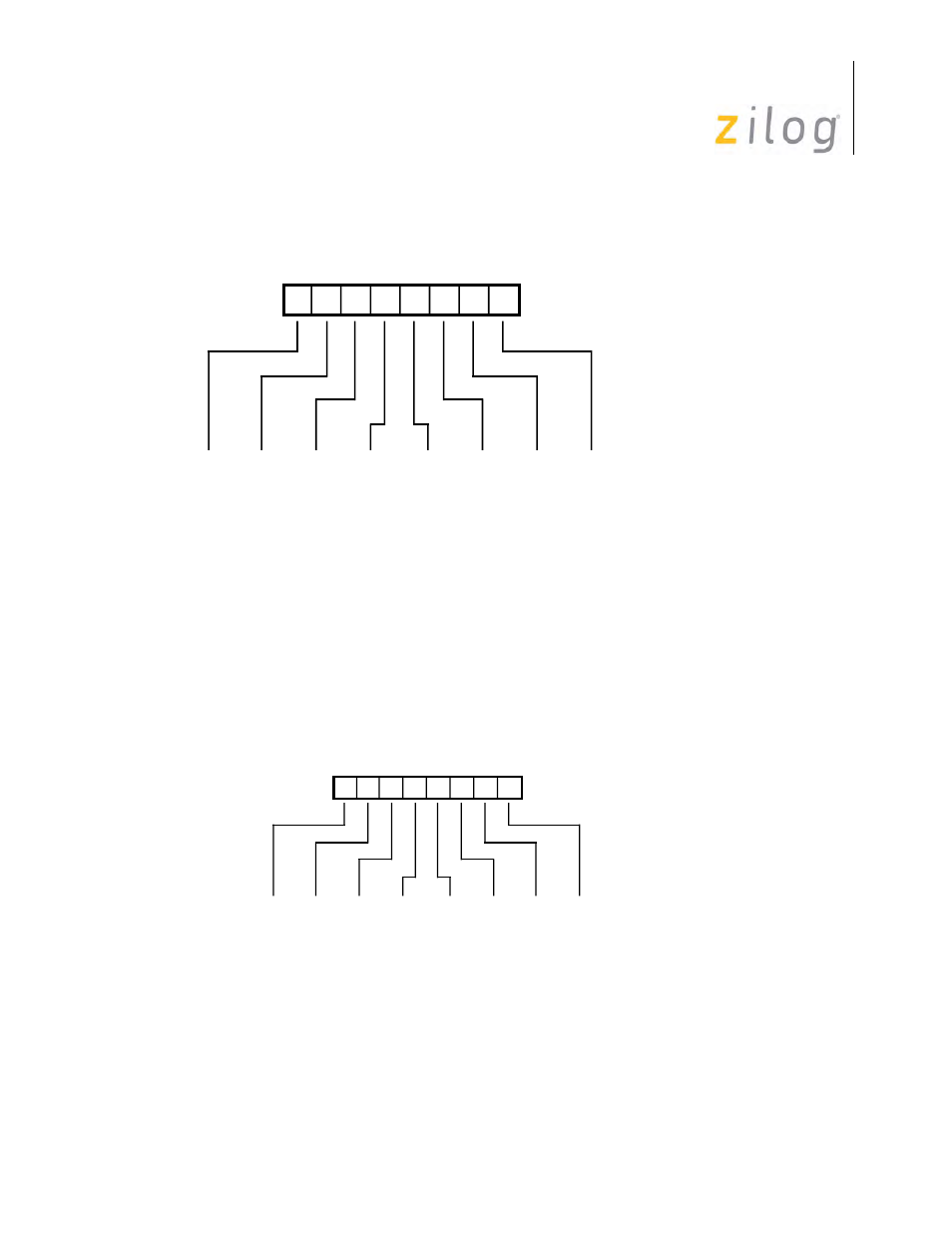
Write Register 6
Write Register 7 (Sync Character or SDLC Flag)
WR7 is programmed to contain the receive sync character in the Monosync mode, a second byte
(the last eight bits) of a 16-bit sync character in the Bisync mode, or a Flag character (01111110) in
the SDLC modes. WR7 holds the receive sync character or a flag if one of the special versions of
the External Sync mode is selected. WR7 is not used in Asynchronous mode. Bit positions for
WR7 are displayed in
.
Write Register 7
Write Register 7 Prime (ESCC only)
This Register is used only with the ESCC. Write Register 7 Prime is located at the same address as
Write Register 7. This register is written to by setting bit D0 of WR15 to a 1. Refer to the descrip-
D7 D6 D5 D4 D3 D2 D1 D0
Write Register 6
Sync3
Sync3
Sync3
1
ADR3
x
Sync2
Sync2
Sync2
1
ADR2
x
Sync1
Sync1
Sync1
1
ADR1
x
Sync0
Sync0
Sync0
1
ADR0
x
Monosync, 8 Bits
Monosync, 6 Bits
Bisync, 16 Bits
Bisync, 12 Bits
SDLC
SDLC (Address Range)
Sync4
Sync4
Sync4
Sync0
ADR4
ADR4
Sync5
Sync5
Sync5
Sync1
ADR5
ADR5
Sync6
Sync0
Sync6
Sync2
ADR6
ADR6
Sync7
Sync1
Sync7
Sync3
ADR7
ADR7
D7 D6 D5 D4 D3 D2 D1 D0
Write Register 7
Sync3
Sync1
Sync11
Sync7
1
Sync2
Sync0
Sync10
Sync6
1
Sync1
x
Sync9
Sync5
1
Sync0
x
Sync8
Sync4
0
Monosync, 8 Bits
Monosync, 6 Bits
Bisync, 16 Bits
Bisync, 12 Bits
SDLC
Sync4
Sync2
Sync12
Sync8
1
Sync5
Sync3
Sync13
Sync9
1
Sync6
Sync4
Sync14
Sync10
1
Sync7
Sync5
Sync15
Sync11
0