Yield monitor 2000, Ag leader technology – Ag Leader Yield Monitor 2000 Operators Manual User Manual
Page 190
System Wiring
Yield Monitor 2000
Ag Leader Technology
June 1997
7-10
System Wiring
Refer to the last page to see a table of all the yield monitor cables and pin-
outs.
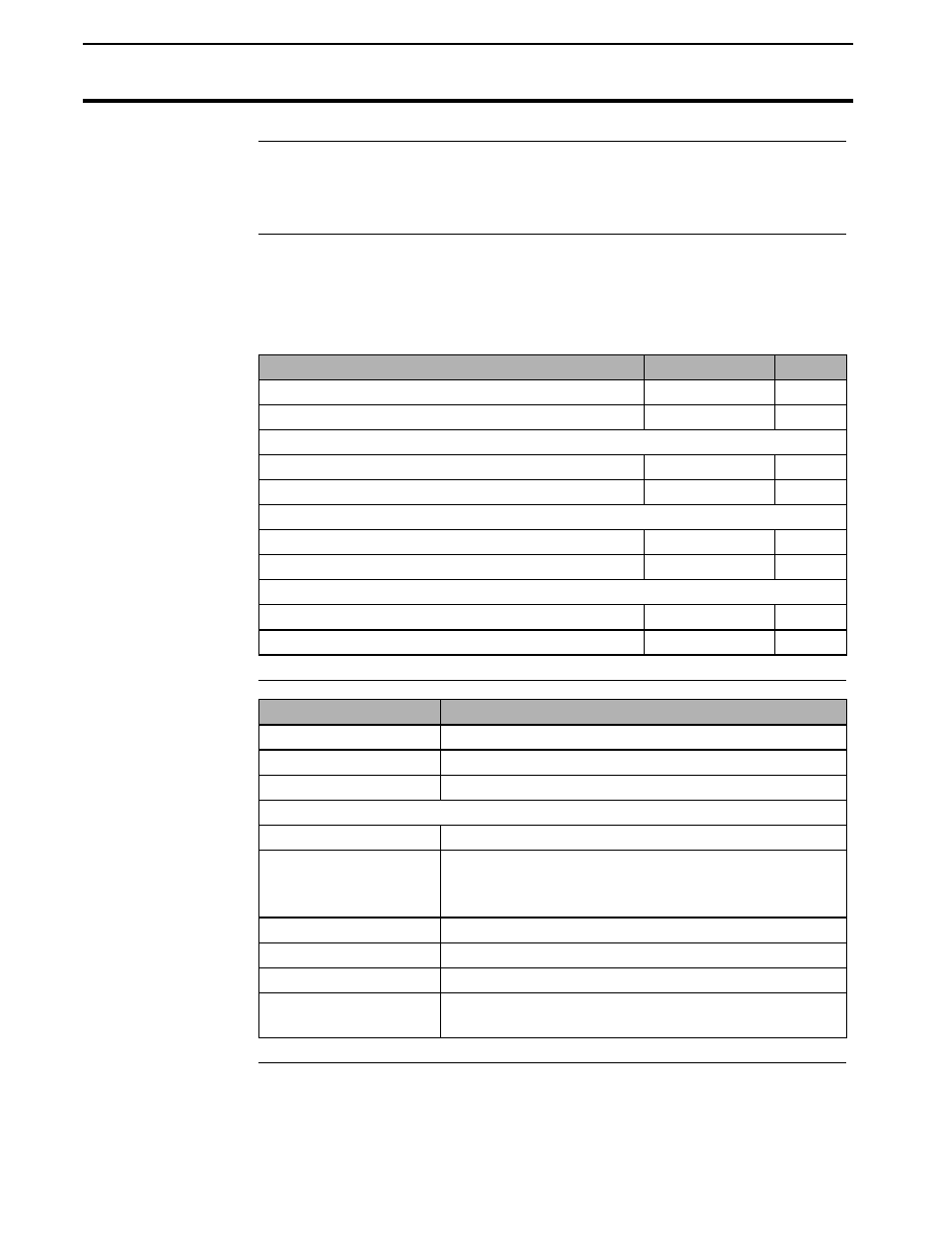
Checking Flow
Sensor
Connections
To check the flow sensor for electrical connection, use an ohmmeter and
check for the following resistance’s (readings can be 1-3 ohms off and still
be good readings):
Check at:
Pins
Ohms
Cab Cable (rectangular 25 pin conn.)
9 + 21
350
Cab Cable (rectangular 25 pin conn.)
8 + 22
375
Distribution Cable (large round 24 pin conn.)
8 + 19
350
Distribution Cable (large round 24 pin conn.)
7 + 20
375
Flow Sensor Ext. Cable (round 9 pin conn.)
2 + 3
350
Flow Sensor Ext. Cable (round 9 pin conn.)
1 + 4
375
Flow Sensor Cable (round 9 pin conn.)
2 + 3
350
Flow Sensor Cable (round 9 pin conn.)
1 + 4
375
Pin-Out of 9-pin
Pin
Signal
Serial Port on
2
RS-232 Transmit (from monitor)
bottom of Monitor
3
RS-232 Receive (into monitor)
5
RS-232 Ground
The following connections exist only on Monitors with S.N.’s above 941000
1
Regulated 5 volts (limit current draw to 50 ma)
4
12 Volt Power (unswitched, reverse polarity
protected, limit current draw to 1
amp)
6
Ground
7
Second RS-232 Transmit (not in use)
8
Second RS-232 Receive (not in use)
9
Auxiliary A/D Input (keep input voltage between
ground and 5 volts)