Yield monitor 2000, Ag leader technology – Ag Leader Yield Monitor 2000 Operators Manual User Manual
Page 135
Yield Monitor 2000
Changing the Program Chip
Ag Leader Technology
June 1997
4-69
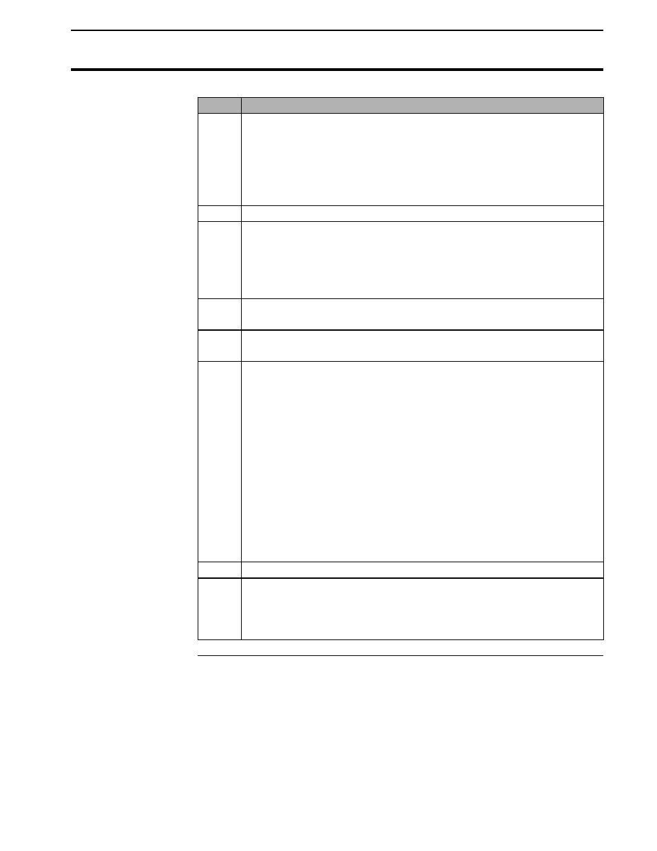
Step
Action
3
Remove the top row of nine screws (three on each of the three
sides) that pass through the outer shell into the front panel of the
box.
Important: Do not remove the two rivets because they act as a
hinge for the front cover.
4
Pull on one of the panel lights to open the front cover.
5
The program chip is in a blue socket on top the small circuit board.
The blue socket contains a program chip that has a label marked
“YM2000 Vx.xx c 199x A.L.T.” Find the two pivoting tabs, one at
each end of the blue socket, which hook over the top of the ends of
the program chip.
6
Use your thumbs to push outward evenly on the two tabs. As you
push them out, they will push the chip up out of the socket.
7
Lift the chip out of the blue socket and place it in the protective case
from which you removed the new chip.
8
Carefully place the new program chip in the blue socket, observing
the following precautions:
•
The notch in the end of the program chip must be positioned
next to the smaller chip labeled FRAP10 or FRAP (notch points
to the left). Installing the chip backwards can damage it.
•
Carefully ensure that all 28 of the chip’s leads are properly
started into the holes in the blue socket. When they are all
aligned, gently push the chip down evenly until the end tabs lock
over the top of the chip.
•
Inspect the leads to make sure they have all engaged properly.
9
Close the front cover and connect the DC power supply.
10
After ensuring that the monitor is working correctly (refer to
Checking the New Chip below for test procedures), turn off the
monitor and reseat the nine screws that hold the front cover to the
outer shell.