Speed sensor type and cal – Seed Hawk Raven 2012 User Manual
Page 43
4
Manual No. 016-3001-003
31
Initial Set Up and Navigation
c.
If the Viper Pro will be used to provide guidance for a towed implement without rate control
capabilities, select the ‘Manual’ option.
Note:
The calibration information presented in following sections must be entered on the serial control
console. To complete the initial set up of the Viper Pro field computer, refer to the Section Setup
section on page 39 to set up the boom or section configuration on the Viper Pro field computer to
match the rate control console.
3.
Touch OK to accept the displayed selection and return to the Main screen.
Speed Sensor Type and Cal
To automatically adjust the rate of applied products for vehicle speed, the field computer must be properly
calibrated for the sensor type providing speed information.
1.
Touch within the Product Control area at the bottom of the main screen.
2.
Touch within the Miscellaneous area on the CAN Controller Status screen.
3.
Select Radar or Wheel for the type of speed sensor connected to the Viper Pro.
Use the Wheel option if a magnetic type, such as a wheel or drive shaft magnet, system is used with the
Viper Pro. Set the speed sensor setting to the Radar option if a radar or GPS unit is sending speed
information to the Viper Pro.
4.
Touch the Speed Cal value and use the on-screen keypad to enter the new value.
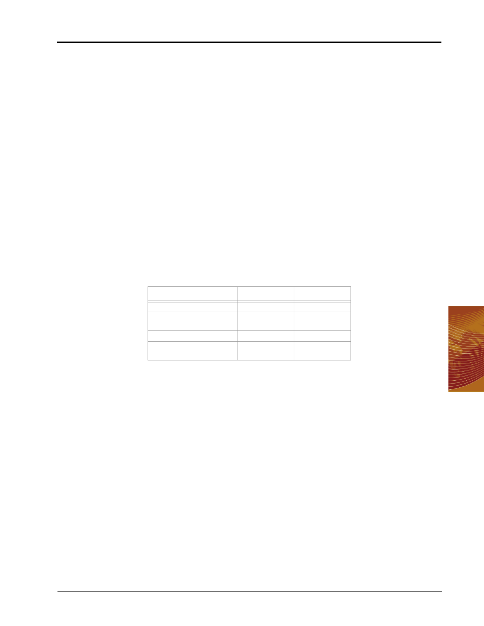
Raven recommends the following speed calibration values for initial system setup.
These values are good starting points and generally yield adequate results, however, the speed cal should
be refined for each specific vehicle and speed sense system. See Appendix C, Calculating the Calibration
Values, for instructions on refining the speed cal value.
Note:
If another source will be used to detect vehicle speed, touch the Calibration Assistance button
and follow the on-screen instructions. Refer to Appendix C, Calculating the Calibration Values for
additional information about the calibration assistance procedure. The procedure outlined in Using
the Calibration Assistance section on page 231, should also be performed to refine or verify the
initial value used with a speed sensor not listed in the above table.
5.
Touch OK to save the currently displayed settings and return to the CAN Controller Status screen.
Sensor Type
US
Metric
Raven Radar
598
152
Raven Invicta or Phoenix
DGPS Receiver
785
199
Wheel Magnets
1000
254
Speedometer Drive Speed
Sensor
612
155