Quencharc wiring example, Standard bus eia-485 communications – Watlow EZ-ZONE RMC User Manual
Page 34
Watlow EZ-ZONE
®
RMC Module
•
31
•
Chapter 2 Install and Wire
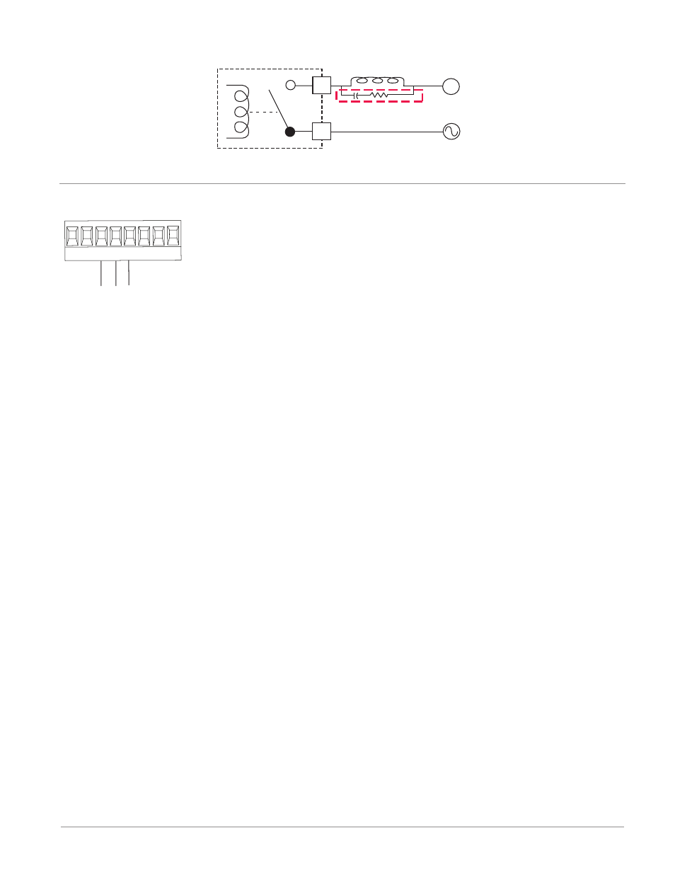
Quencharc Wiring Example
In this example the Quencharc
circuit (Watlow part# 0804-0147-
0000) is used to protect the RMC
internal circuitry from the counter
electromagnetic force from the in-
ductive user load when de-enger-
gized. It is recommended that this
or an equivalent Quencharc be
used when connecting inductive
loads to RMC outputs.
Quencharc
User Load
N
L_
K_
Standard Bus EIA-485 Communications
T-/R-
common
Slot C
T+/R+
98 99
CF CD CE
CZ CX CY
• Wire T-/R- to the A
terminal of the EIA-
485 port.
• Wire T+/R+ to the B
terminal of the EIA-
485 port.
• Wire common to the
common terminal of
the EIA-485 port.
• Do not route network
wires with power
wires. Connect net-
work wires in daisy-
chain fashion when
connecting multiple
devices in a network.
• A 120 Ω termination resis-
tor may be required across
T+/R+ and T-/R-, placed on
the last controller on the
network.
• Do not connect more than
16 EZ-ZONE RM control-
lers on a network.
• maximum network length:
1,200 meters (4,000 feet)
• 1/8th unit load on EIA-485
bus
RMCxxxxxxxx(A)xx
* All models include Standard
Bus communications
Note:
Do not leave a USB to EIA-485 converter connected to Standard Bus without
power (i.e., disconnecting the USB end from the computer while leaving the
converter connected on Standard Bus). Disturbance on the Standard Bus may
occur.