Watlow ez-zone, Rmc module, Chapter 8 appendix – Watlow EZ-ZONE RMC User Manual
Page 230
Watlow EZ-ZONE
®
RMC Module
•
227
•
Chapter 8 Appendix
Code Number
1
= Control with universal input
2
= Control with thermistor input
3
= Ramp/Soak control with universal input (R/S applies to all
loops in module)
4
= Ramp/Soak control with thermistor input (R/S applies to all
loops in module)
5
= Limit with universal input(Only valid Output 1 and 2, options
will be B, F, L)
6
=
Limit with thermistor input(Only valid Output 1 and 2, options
will be B, F, L)
7
= Current transformer input(NOT valid Output 1 and 2, options
are N, P, R, S)
9
= Custom
Output 1
Output 2
A = None
None
B = None
Mechanical relay 5A, Form A
U = Switched dc/open collector
None
D = Switched dc/open collector
NO-ARC 15A power control
E = Switched dc/open collector
Switched dc
F
= Switched dc/open collector
Mechanical relay 5A, Form A
G = Switched dc/open collector
SSR Form A, 0.5A
H = Mechanical relay 5A, Form
None
J
= Mechanical relay 5A, Form C NO-ARC 15A power control
K = Mechanical relay 5A, Form C Switched dc
L
= Mechanical relay 5A, Form C Mechanical relay 5A, Form A
M = Mechanical relay 5A, Form C SSR Form A, 0.5A
N = Universal process
None
P = Universal process
Switched dc
R = Universal process
Mechanical relay 5A, Form A
S = Universal process
SSR Form A, 0.5A
T
= None
SSR Form A, 0.5A
Y = SSR Form A, 0.5A
NO-ARC 15A power control
Z = SSR Form A, 0.5A
SSR Form A, 0.5A
A = None
1
= Control with universal input
2
= Control with thermistor input
5
= Limit with universal input (Only valid Output 3 and 4, options
will be B, F ,L)
6
= Limit with thermistor input (Only valid Output 3 and 4, options
will be B, F, L)
7
= Current transformer input (Not valid Output 3 and 4, options
are N, P, R, S)
Output 3
Output 4
A = None
None
B = None
Mechanical relay 5A, Form A
U = Switched dc/open collector
None
D = Switched dc/open collector
NO-ARC 15A power control
E
= Switched dc/open collector
Switched dc
F
= Switched dc/open collector
Mechanical relay 5A, Form A
G = Switched dc/open collector
SSR Form A, 0.5A
H = Mechanical relay 5A, Form C
None
J
= Mechanical relay 5A, Form C
NO-ARC 15A power control
K = Mechanical relay 5A, Form C
Switched dc
L
= Mechanical relay 5A, Form C
Mechanical relay 5A, Form A
M = Mechanical relay 5A, Form C
SSR Form A, 0.5A
N = Universal process
None
P = Universal process
Switched dc
R = Universal process
Mechanical relay 5A, Form A
S = Universal process
SSR Form A, 0.5A
T
= None
SSR Form A, 0.5A
Y = SSR Form A, 0.5A
NO-ARC 15A power control
Z
= SSR Form A, 0.5A
SSR Form A, 0.5A
A = None
1
= Control with universal input
2
= Control with thermistor input
5
= Limit with universal input(Only valid Output 5 and 6, options
will be B, F, L)
6
= Limit with thermistor input(Only valid Output 5 and 6, options
will be B, F, L)
7
= Current transformer input(Not valid Output 5 and 6, options
are N, P, R, S)
Firmware, Overlays, Parameter Settings
AA = Standard
AB = Replacement connectors hardware only for the entered
model number
12 = Class 1, Div. 2 (not available with integrated limit controller or
mechanical relay options)
XX = Custom, Locked Firmware
A = Standard bus
1
=
Standard bus and Modbus
®
RTU 485
A = Right angle screw connector (standard)
F
= Front screw connector
Output 7
Output 8
A = None
None
B = None
Mechanical relay 5A, Form A
U = Switched dc/open collector
None
D = Switched dc/open collector
NO-ARC 15A power control
E = Switched dc/open collector
Switched dc
F
= Switched dc/open collector
Mechanical relay 5A, Form A
G = Switched dc/open collector
SSR Form A, 0.5A
H = Mechanical relay 5A, Form C None
J
= Mechanical relay 5A, Form C NO-ARC 15A power control
K = Mechanical relay 5A, Form C Switched dc
L
= Mechanical relay 5A, Form C Mechanical relay 5A, Form A
M = Mechanical relay 5A, Form C SSR Form A, 0.5A
N = Universal process
None
P = Universal process
Switched dc
R = Universal process
Mechanical relay 5A, Form A
S = Universal process
SSR Form A, 0.5A
T
= None
SSR Form A, 0.5A
Y = SSR Form A, 0.5A
NO-ARC 15A power control
Z = SSR Form A, 0.5A
SSR Form A, 0.5A
C = 6 digital inputs/outputs
(Valid option only if Input 4 selection = A)
A = None
1
= Control with universal input
2
= Control with thermistor input
5
= Limit with universal input(Only valid Output 7 and 8, options
will be B, F, L)
6
= Limit with thermistor input(Only valid Output 7 and 8, options
will be B, F, L)
7
= Current transformer input(Not valid Output 7 and 8, options
are N, P, R, S)
Output 5
Output 6
A = None
None
B = None
Mechanical relay 5A, Form A
U = Switched dc/open collector
None
D = Switched dc/open collector
NO-ARC 15A power control
E = Switched dc/open collector
Switched dc
F
= Switched dc/open collector
Mechanical relay 5A, Form A
G = Switched dc/open collector
SSR Form A, 0.5A
H = Mechanical relay 5A, Form C None
J
= Mechanical relay 5A, Form C NO-ARC 15A power control
K = Mechanical relay 5A, Form C Switched dc
L
= Mechanical relay 5A, Form C Mechanical relay 5A, Form A
M = Mechanical relay 5A, Form C SSR Form A, 0.5A
N = Universal process
None
P = Universal process
Switched dc
R = Universal process
Mechanical relay 5A, Form A
S = Universal process
SSR Form A, 0.5A
T
= None
SSR Form A, 0.5A
Y = SSR Form A, 0.5A
NO-ARC 15A power control
Z = SSR Form A, 0.5A
SSR Form A, 0.5A
RM
C
EZ-ZONE
Rail Mount
Additional
Options
Enhanced
Options
Connector
Style
Input 2
Outputs
1 & 2
Hardware
Options
Input 1
Primary
Function
Control
Module
Outputs
3 & 4
Hardware
Options
Input 3
Outputs
5 & 6
Hardware
Options
Outputs
7 & 8
Hardware
Options
Input 4
Input 1
Output 1 and 2 Hardware Options
Output 5 and 6 Hardware Options
Output 7 and 8 Hardware Options
Output 3 and 4 Hardware Options
Input 2
Input 3
Input 4
Additional Options
Enhanced Options
Connector Style
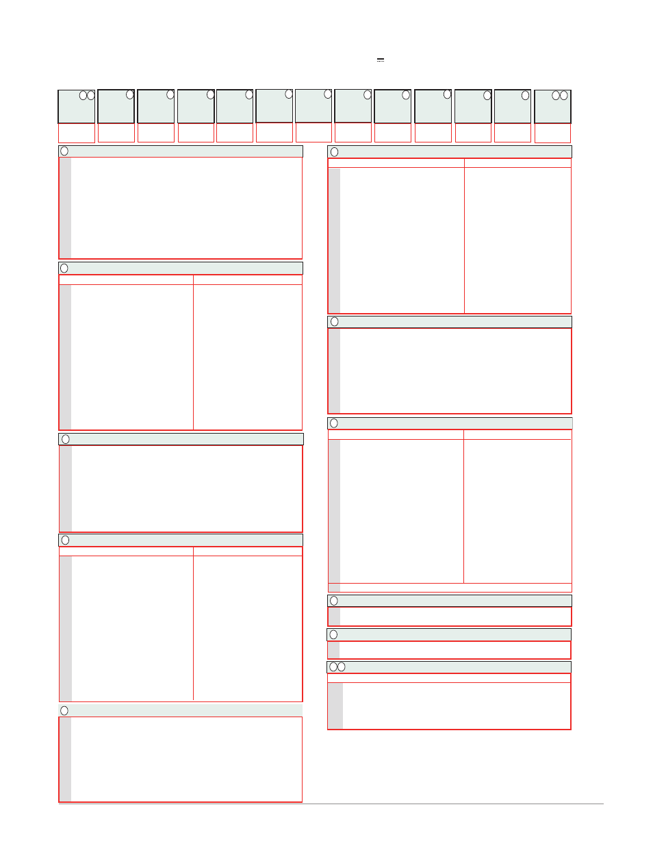
EZ-ZONE Rail-Mount Control Module Ordering Information
Control module requires a Class 2 or SELV power supply 20.4 to 30.8 V ~(ac) / (dc), communication port for configuration
with EZ-ZONE Configurator software.
R
= Auxillary 2nd Input (Universal Input)
P
= Auxillary 2nd Input (Thermistor Input)
R
= Auxillary 2nd Input (Universal Input)
P
= Auxillary 2nd Input (Thermistor Input)
R
= Auxillary 2nd Input (Universal Input)
P
= Auxillary 2nd Input (Thermistor Input)
3
4
5
6
7
8
9
10
2
11
12
13
14 15
1
4
5
6
7
8
9
10
11
12
13
14 15