Communications, Input 1, 2, 3, 4 thermocouple – Watlow EZ-ZONE RMC User Manual
Page 25
Warning:
ç
Use National Electric (NEC) or other
country-specific standard wiring and
safety practices when wiring and
connecting this controller to a power
source and to electrical sensors or pe-
ripheral devices. Failure to do so may
result in damage to equipment and
property, and/or injury or loss of life.
Note:
Maximum wire size termination and
torque rating:
• 0.0507 to 3.30 mm2 (30 to 12 AWG)
single-wire termination or two 1.31
mm2 (16 AWG)
• 0.8 Nm (7.0 in-lb.) torque
Note:
Adjacent terminals may be labeled
differently, depending on the model
number.
Note:
To prevent damage to the controller,
do not connect wires to unused ter-
minals.
Note:
Maintain electrical isolation between
digital input-outputs, switched dc/open
collector outputs and process outputs
to prevent ground loops.
Note:
If the last two digits of the part number
are "12", this equipment is suitable for
use in CLASS I, DIVISION 2, Groups A,
B, C and D or Non-Hazardous locations
only. Temperature Code T4
Warning:
ç
Explosion Hazard – Substitution of
component may impair suitability for
CLASS I, DIVISION 2.
Warning:
ç
Explosion Hazard - Do not disconnect
while the circuit is live or unless the
area is known to be free of ignitable
concentrations of flammable sub-
stances.
Watlow EZ-ZONE
®
RMC Module
•
22
•
Chapter 2 Install and Wire
Controller Module Wiring (RMCxxxxxxxxxxxx)
Low Power
RMC - All Model Numbers
98 99
power
• 20.4 to 30.8 V Å (ac) / Î (dc) 14VA
• 47 to 63 Hz
• Controller module power consumption, 7 Watts maxi-
mum
• 31 Watts maximum power available for P/S part
#:0847-0299-0000
• 60 Watts maximum power available for P/S part
#:0847-0300-0000
• 91 Watts maximum power available for P/S part
#:0847-0301-0000
• Class 2 or Safety Extra Low Voltage (SELV) power
source required to meet UL compliance standards
Communications
RMC Part # Digit 13 is A
Standard Bus
Common
T- / R-
Inter-module Bus
Common
-
+
T+ / R+
CF CD CE CZ CX CY
Slot C
• CF, CD, CE - Standard Bus EIA485 Communications
• CZ, CX, CY - Inter-module Bus EIA485 Communica-
tions
• Do not route network wires with power wires. Connect
network wires in daisy-chain fashion when connecting
multiple devices in a network
Communications
RMC Part # Digit 13 is 1
T+ / R+
Modb
us
C
ommon
T- / R-
Int
er
-module Bus
C
ommon
+
-
CC CA CB CZ CX CY
Slot C
• CC, CA, CB - Modbus and Standard Bus EIA485 Com-
munications (selectable via push button under zone ad-
dress)
• CZ, CX, CY - Inter-module Bus EIA485 Communica-
tions
• Do not route network wires with power wires. Connect
network wires in daisy-chain fashion when connecting
multiple devices in a network
Modbus-IDA
Terminal
EIA/TIA-
485 Name
Watlow Terminal
Label
Function
DO
A
CA or CD
T-/R-
D1
B
CB or CE
T+/R+
common
common
CC or CF
common
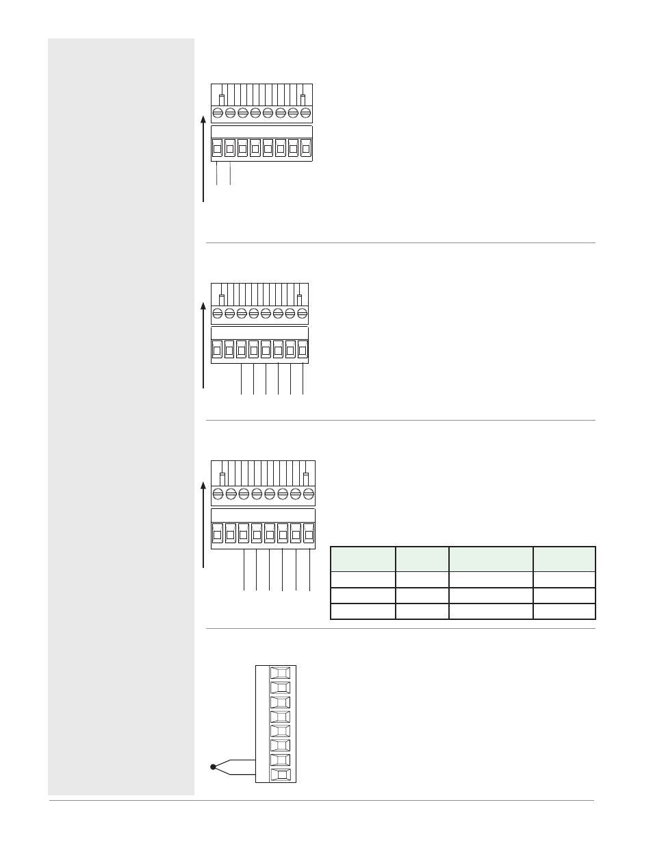
Input 1, 2, 3, 4 Thermocouple
RMC
Part # Digits 4, 6, 8, 10
-
+
S_
R_
Slot A, B, D, E
• >20 MΩ input impedance
• 3 microampere open-sensor detection
• Thermocouples are polarity sensitive. The negative lead
(usually red) must be connected to S terminal
• To reduce errors, the extension wire for thermocouples
must be of the same alloy as the thermocouple.
Input 1: RMC(1,3,5)xxxxxxxxxxx
Input 2: RMCxx(1,5)xxxxxxxxx
Input 3: RMCxxxx(1,5)xxxxxxx
Input 4: RMCxxxxxx(1,5)xxxxx