Cascade control, Compressor control, Differential control – Watlow EZ-ZONE RMC User Manual
Page 165
Watlow EZ-ZONE
®
RMC Module
•
162
•
Chapter 7 Features
Cascade Control
Cascade control is a control strategy in which one
control loop provides the set point for another loop. It
allows the process or part temperature to be reached
quickly while minimizing overshoot. Cascade is used
to optimize the performance of thermal systems with
long lag times. The graph on the next page illus-
trates a thermal system with a long lag time.
Curve A represents a single loop control system
with PID parameters that allow a maximum heat
up rate. Too much energy is introduced and the
set point is overshot. In most systems with long lag
time, the process value may never settle out to an ac-
ceptable error. Curve C represents a single control
system tuned to minimize overshoot. This results in
unacceptable heat up rates, taking hours to reach
the final value. Curve B shows a cascade system that
limits the energy introduced into the system, allow-
ing an optimal heat up rate with minimal overshoot.
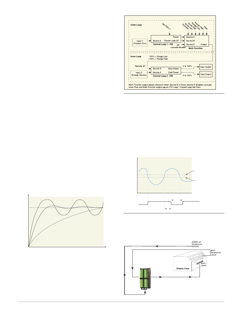
Cascade control uses two control loops (outer and
inner) to control the process. The outer loop (analog
input 2) monitors the process or part temperature,
which is then compared to the closed loop set point.
The result of the comparison, the error signal, is
acted on by the PID settings in the cascade outer
loop, which then generates a power level for the outer
loop. The set point for the inner loop is determined
by the outer loop power level. The inner loop input
(any input) monitors the energy source (heating and
cooling), which is compared to the inner loop set
point generated by the outer loop. The result of the
comparison, the error signal, is acted on by the PID
settings in the cascade inner loop, which generates
an output power level between -100% to +100%. If
the power level is positive the heat will be on; if the
power level is negative the cool will come on. Power
from the energy sources are supplied by the outputs
of choice.
Time
Temperature
Cascade
Curve A (PID)
Set
Point
Curve B (Cascade)
Curve C (Single-control)
Cascade
Compressor Control
The compressor control can save wear on a compres-
sor and prevent it from locking up from short cycling.
A bypass valve operated by a control output regu-
lates how the process is cooled, while another output
switches the compressor on and off. The compressor
will not turn on until the output power exceeds the
Compressor On % Power for a time longer than the
Compressor On Delay. The compressor will not turn
off until the output power exceeds the Compressor
Off % Power for a time longer than the Compressor
Off Delay.
0% Compressor
On Power
Off
On
100%
2%
0%
-100%
Compressor On Delay = 45 Seconds
Compressor Off Delay = 20 Seconds
2% Compressor
Off Power
Time In Seconds
% Power
Heat
Cool
Compressor
Differential Control
After configuring the appropriate inputs and their
associated internal functions Differential Control al-
lows the RMC to drive an output based on the differ-
ence between those analog inputs.
Input 1
Input 2
Output 1