On-off control – Watlow EZ-ZONE RMC User Manual
Page 162
Watlow EZ-ZONE
®
RMC Module
•
159
•
Chapter 7 Features
that allows the user to directly set the power level
to the controller’s output load. No adjustments of the
output power level occur based on temperature or
closed loop set point in this mode.
In auto mode, the controller monitors the input
to determine if closed-loop control is possible. The
controller checks to make certain a functioning sen-
sor is providing a valid input signal. If a valid input
signal is present, the controller will perform closed-
loop control. Closed-loop control uses a process sen-
sor to determine the difference between the process
value and the closed loop set point. Then the control-
ler applies power to a control output load to reduce
that difference. If a valid input signal is not present,
the controller will indicate an input error message
in the upper display and [Attn] in the lower display
and respond to the failure according to the setting of
Input Error Failure [FAiL]. You can configure the
controller to perform a “bumpless” transfer [bPLS],
switch power to output a preset fixed level [MAn], or
turn the output power off.
Bumpless transfer will allow the controller to
transfer to the manual mode using the last power
value calculated in the auto mode if the process had
stabilized at a ±5 percent output power level for the
time interval of Time Integral or 10 seconds, which
ever is larger (Operations Page, Loop), prior to sensor
failure, and that power level is less than 75 percent.
Reverse Bumpless functionality will take effect
when the control is changed from Manual to Auto
mode. The control will preload the Open Loop Set
Point value into the Integral Term, which will allow
for a bumpless transition. The normal PID action will
then take over to control the output to the Closed
Loop Set Point value.
Time
Temperature
Bumpless Transfer
40%
Sensor
Break
2 minutes
Locks in
Output
Power
0%
Set Point
Actual Temperature
Output Power
Power
100%
Input Error Latching [`i;Er] (Setup Page, Ana-
log Input Menu) determines the controller’s response
once a valid input signal returns to the controller.
If latching is on, then the controller will continue
to indicate an input error until the error is cleared.
To clear a latched alarm, press the Advance Key
‰
then the Up Key ¿.
If latching is off, the controller will automatically
clear the input error and return to reading the tem-
perature. If the controller was in the auto mode when
the input error occurred, it will resume closed-loop
control. If the controller was in manual mode when
the error occurred, the controller will remain in
open-loop control.
The Manual Control Indicator Light % is on when
the controller is operating in manual mode.
If using an RUI switching between modes is easy
if the Control Mode [`C;M] parameter is selected to
appear in the Home Page.
To transfer to manual mode from auto mode,
press the Advance Key
‰
until [`C;M] appears in
the lower display. The upper display will display
[AUto]
for auto mode. Use the Up ¿ or Down ¯ keys
to select [Man]. The manual set point value will be
recalled from the last manual operation.
To transfer to auto mode from manual mode,
press the Advance Key
‰
until [`C;M] appears in
the lower display. The upper display will display
[MAn]
for manual mode. Use the Up ¿ or Down ¯
keys to select [AUto]. The automatic set point value
will be recalled from the last automatic operation.
Changes take effect after three seconds or imme-
diately upon pressing either the Advance Key
‰
or
the Infinity Key ˆ.
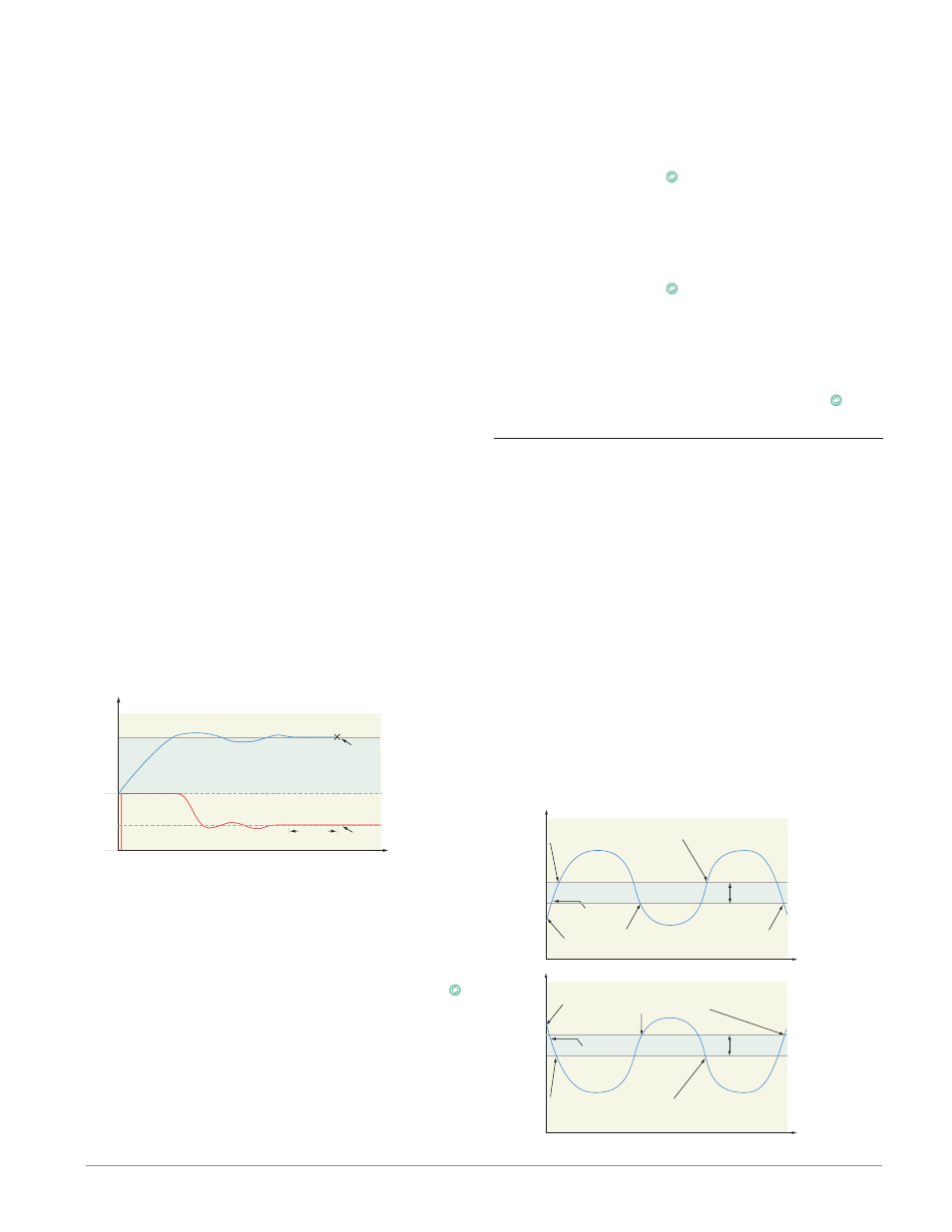
On-Off Control
On-off control switches the output either full on or
full off, depending on the input, set point and hys-
teresis values. The hysteresis value indicates the
amount the process value must deviate from the set
point to turn on the output. Increasing the value de-
creases the number of times the output will cycle.
Decreasing hysteresis improves controllability. With
hysteresis set to 0, the process value would stay clos-
er to the set point, but the output would switch on
and off more frequently, and may result in the output
“chattering.” On-off control can be selected with Heat
Algorithm [`h;Ag] or Cool Algorithm [`C;Ag] (Setup
Page, Loop Menu). On-off hysteresis can be set with
Heat Hysteresis [`h;hY] or Cool Hysteresis [`C;hY]
(Operations Page, Loop Menu).
Note:
Input Error Failure Mode
[faIl]
does not function in
on-off control mode. The output goes off.
Set Point
Time
Temperature
The heating action switches off when the process
temperature rises above the set point.
The heating action
switches on at startup.
Hysteresis
Process Temperature
Hysteresis
Time
Temperature
On/Off System Cycles
The cooling action
switches
on at startup.
Process Temperature
The cooling action switches on when
the process temperature rises above
the set point plus the hysteresis.
Set Point
The heating action switches on when the process temperature
drops below the set point minus the hysteresis.
The cooling action switches off when the process
temperature drops below the set point.