Watlow ez-zone, Rmc module, Chapter 1 overview – Watlow EZ-ZONE RMC User Manual
Page 15
Watlow EZ-ZONE
®
RMC Module
•
12
•
Chapter 1 Overview
Some input/output combinations not possible, see ordering matrix
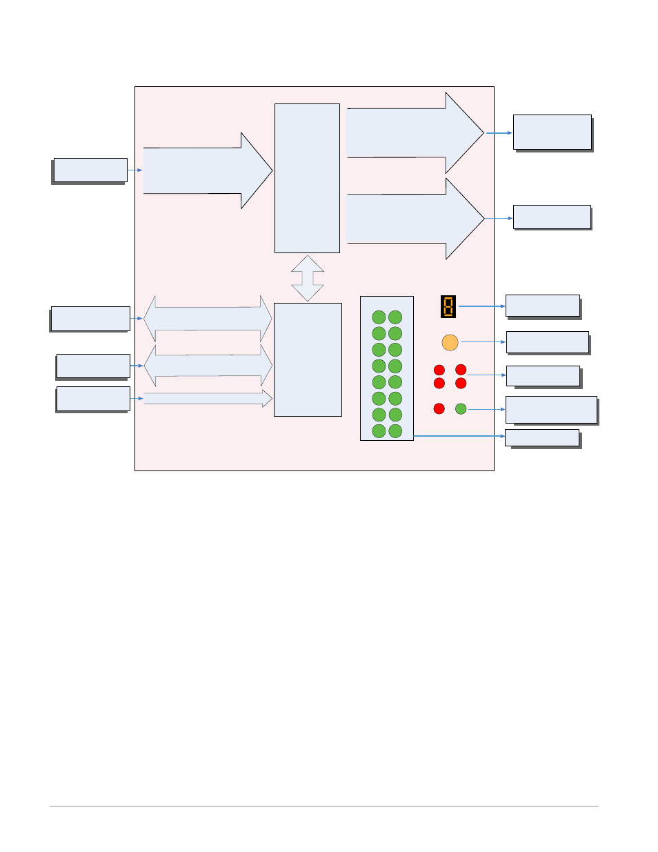
Zone and Status
LED
Zone Selection
Output Status
LEDs
2
3
4
5
6
1
10
11
12
13
14
9
7
8
15
16
Button
D
E
B
A
S
M
None, 15A NO-ARC Form A,
Switched dc, 5A Mechanical Relay
Form A, or 0.5A Solid-State Relay
Form A
Output 2, 4, 6, 8
Off, Heat, Cool,
Alarm, Retransmit,
Duplex, Event or Limit
Off, Heat, Cool,
Alarm, Event or Limit
None, CT, Thermocouple, RTD (100, 1k),
Thermistor (5k, 10K, 20k, 40k), Process
(mV, V, mA) or 1k Potentionmeter
Analog Input 1, 2, 3, 4
(When ordered, all
loops have Ramp/
Soak, max 25 files
& 400 steps.)
Current
Transformer
Sense (CT),
Limit or
PID Controller
Slot A, B, D or E
(optional)
EIA - 485 Communications
Standard Bus
(optional Modbus RTU)
Inter-module Bus
Class 1 Div
II not available
with mechanical relay
outputs.
Indicates Zone
Address
Push to select Zone
Address and Protocol
Card Status
Slots A, B, D, E
Indicates I/O
Status
Indicates communications
activity (Modbus or Stan-
dard Bus)
Input Sensor
RUI,
PC, PLC or HMI
Other RM Modules
Power Supply
Modbus RTU
Address 1 - 16
Standard Bus
Zone 1 - 16
Supervisory &
Power Board
Slot C
Output
Function
Input
Function
If Limit, this output
must be Limit.
None, Switched dc/Open Collector,
5A Mechanical Relay Form C, Process,
or 0.5A Solid-State Relay Form A
Output 1, 3, 5, 7
20.4 to 30.8 Vac or Vdc
EZ-ZONE RM-Control Module - System Diagram
without 6-Digital Input/Output card in slot E