Outputs, Range high and range low, Receiving a remote set point – Watlow EZ-ZONE RMC User Manual
Page 160: Ten point linearization, No-arc relay
Watlow EZ-ZONE
®
RMC Module
•
157
•
Chapter 7 Features
Select the low and high values with Scale Low
[`S;Lo]
and Scale High [`S;hi]. Select the displayed
range with Range Low [`r;Lo] and Range High
[`r;hi]
(Setup Page, Analog Input Menu).
Range High and Range Low
With a process input, you must choose a value to rep-
resent the low and high ends of the current or voltage
range. Choosing these values allows the controller’s
display to be scaled into the actual working units of
measurement. For example, the analog input from a
humidity transmitter could represent 0 to 100 per-
cent relative humidity as a process signal of 4 to 20
mA. Low scale would be set to 0 to represent 4 mA
and high scale set to 100 to represent 20 mA. The in-
dication on the display would then represent percent
humidity and range from 0 to 100 percent with an
input of 4 to 20 mA.
Select the low and high values with Range Low
[`r;Lo]
and Range High [`r;hi] (Setup Page, Analog
Input Menu).
Receiving a Remote Set Point
The remote set point feature allows the controller
to use a thermocouple, RTD, 1k potentiometer or
process signal (from any RM module) as the second
input to establish the set point, which allows its set
point to be manipulated by an external source. A
common application would use one ramping controller
with a set-point retransmit output to ramp multiple
controllers using the remote set point. Or you could
use an analog output from a PLC to send set point
values to an EZ-ZONE RMC. The controller must
have at least two process inputs to use the remote set
point feature.
You may select between local and remote set
points at the front panel, with an event input, from
a remote computer using the communications fea-
ture or from an external switch using an event input.
Make sure all input and output impedances are com-
patible.
Switch to the remote set point with Remote En-
able [`r;En] (Operations Page, Loop Menu). Select
whether the remote set point controls an open- or
closed-loop set point with Remote Set Point Type
[`r;ty]
.
Assign the function of switching to a remote set
point to an Action Function [``Fn] (Setup Page, Ac-
tion Menu).
Assign the function of switching to a remote set
point to the EZ Key with Digital Input Function
[``Fn]
(Setup Page, Function Key Menu).
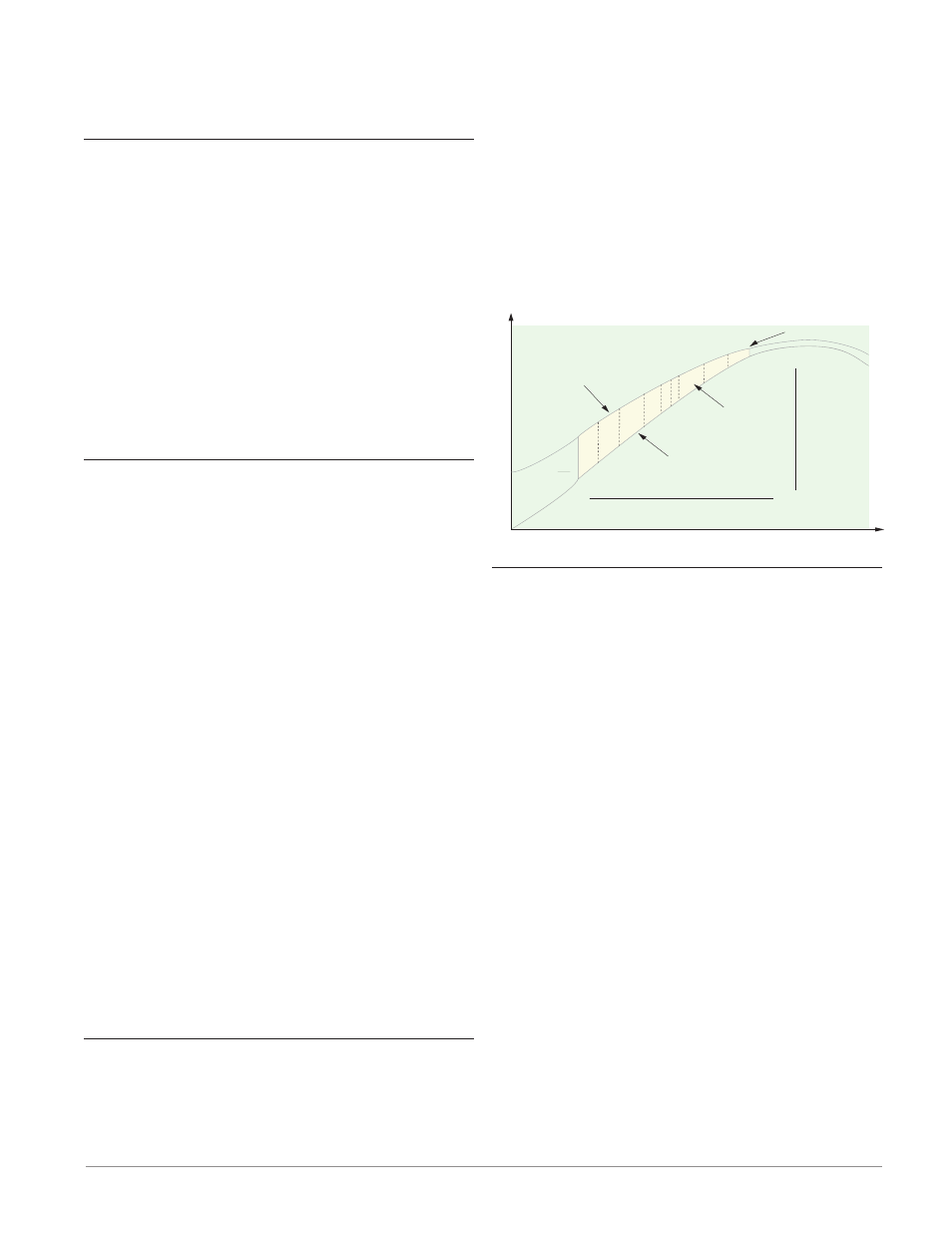
Ten Point Linearization
The linearization function allows a user to re-linear-
ize a value read from an analog source. The function
selections are Off, Interpolated and Stepped. When
set to Off the output will match the Source A value
plus offset. There are 10 data points used to compen-
sate for differences between the source value read
(input point) and the desired value (output point).
Multiple data points enable compensation for non-
linear differences between the sensor readings and
target process values over the thermal or process sys-
tem operating range. Sensor reading differences can
be caused by sensor placement, tolerances, an inaccu-
rate sensor or lead resistance.
The user specifies the unit of measurement and
then each data point by entering an input point value
and a corresponding output point value. Each data
point must be incrementally higher than the previous
point. The linearization function will interpolate data
points linearly in between specified data points.
2
3
4
5 6
7
8
9
Reading from Sensor
without Linearization
(Actual Value)
Input Point 1
Output Point 1
Input Point 10
Output Point 10
Offset Zone
Reading from Sensor
with Linearization
(Displayed Value)
No Offset
T
emperature
Time
Outputs
NO-ARC Relay
A NO-ARC relay provides a significant improvement
in the life of the output relay over conventional re-
lays.
Conventional mechanical relays have an expected
life of 100,000 cycles at the rated full-load current.
The shorter life for conventional relays is due to the
fact that when contacts open while current is flowing
metal degradation occurs. This action produces un-
avoidable electrical arcing causing metal to transfer
from one contact to the other. The arcing conditions
continue on each subsequent contact opening until
over time the resistance through the contacts in-
creases causing the contacts to increase in tempera-
ture. Eventually, the contacts will weld together and
the relay remains in the on state.
The Watlow NO-ARC relay is a hybrid relay. It us-
es a mechanical relay for the current load and a triac
(solid-state switch) to carry the turn-on and turn-off
currents. NO-ARC relays extend the life of the relay
more than two million cycles at the rated full-load
current.
Although a NO-ARC relay has significant life ad-
vantages, a few precautions must be followed for ac-
ceptable usage:
Do not use:
• Hybrid relays for limit contactors. A limit or
safety device must provide a positive mechanical
break on all hot legs simultaneously;