Digital inputs/outputs 7 through 12, Digital inputs 7 through 12 – Watlow EZ-ZONE RMC User Manual
Page 28
Watlow EZ-ZONE
®
RMC Module
•
25
•
Chapter 2 Install and Wire
Warning:
ç
Use National Electric (NEC) or other
country-specific standard wiring and
safety practices when wiring and
connecting this controller to a power
source and to electrical sensors or pe-
ripheral devices. Failure to do so may
result in damage to equipment and
property, and/or injury or loss of life.
Note:
Maximum wire size termination and
torque rating:
• 0.0507 to 3.30 mm2 (30 to 12 AWG)
single-wire termination or two 1.31
mm2 (16 AWG)
• 0.8 Nm (7.0 in-lb.) torque
Note:
Adjacent terminals may be labeled
differently, depending on the model
number.
Note:
To prevent damage to the controller,
do not connect wires to unused ter-
minals.
Note:
Maintain electrical isolation between
digital input-outputs, switched dc/open
collector outputs and process outputs
to prevent ground loops.
Note:
If the last two digits of the part number
are "12", this equipment is suitable for
use in CLASS I, DIVISION 2, Groups A,
B, C and D or Non-Hazardous locations
only. Temperature Code T4
Warning:
ç
Explosion Hazard – Substitution of
component may impair suitability for
CLASS I, DIVISION 2.
Warning:
ç
Explosion Hazard - Do not disconnect
while the circuit is live or unless the
area is known to be free of ignitable
concentrations of flammable sub-
stances.
Suppressor Note:
Switching pilot duty inductive loads (re-
lay coils, solenoids, etc .) with the me-
chanical relay, solid state relay or open
collector output options requires use of
an R .C . suppressor
.
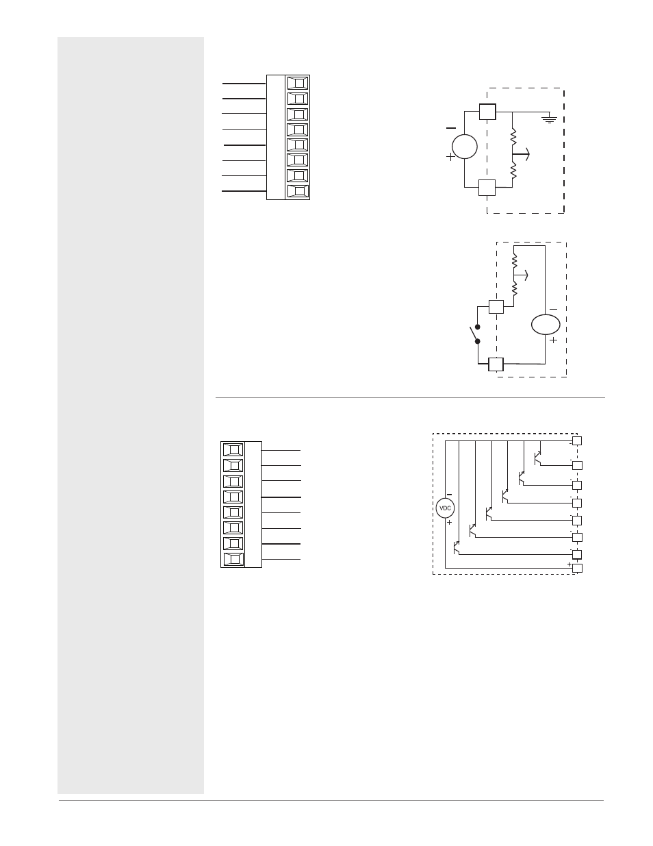
Digital Inputs 7 through 12
RMC Part # Digit 11 is C
Common
DC Input
B7
D7
D8
D9
D10
D11
D12
Z7
Slot E
Internal Supply
DC Input
DC Input
DC Input
DC Input
DC Input
Digital Input Event Con-
ditions
• Dry Contact
- Input inactive when >
100KΩ
- Input active when <
50Ω
• Voltage
- Input inactive when <
2V
- Input active when >
3V
• Six user configurable
Digital Inputs/outputs
per slot
- Slot E DIO 7-12
Voltage Input
Vdc
common
B
_
D
_
Dry Contact
24 Vdc
_
Z
_
D
Digital Inputs/Outputs 7 through 12
RMC Part # Digit 11 is C
Common
Collector out
Collector out
B7
D7
D8
D9
D10
D11
D12
Z7
Slot E
Collector out
Collector out
Collector out
Collector out
Internal Supply
• Maximum switched
voltage is 32VÎ (dc)
• Internal supply pro-
vides a constant pow-
er output of 750mW
• Maximum output
sink current per out-
put is 1.5A (external
class 2 or *SELV sup-
ply required)
• Total sink current for
all outputs not to ex-
ceed 8A
• Do not connect out-
puts in parallel
*Safety Extra Low Volt-
age
Common
Internal
Supply
D12
D11
D10
D9
D8
B7
D7
Z7