Input 1, 2, 3, 4 thermistor, Input 1, 2, 3, 4 rtd, Input 1, 2, 3, 4 process – Watlow EZ-ZONE RMC User Manual
Page 26
Watlow EZ-ZONE
®
RMC Module
•
23
•
Chapter 2 Install and Wire
Warning:
ç
Use National Electric (NEC) or other
country-specific standard wiring and
safety practices when wiring and
connecting this controller to a power
source and to electrical sensors or pe-
ripheral devices. Failure to do so may
result in damage to equipment and
property, and/or injury or loss of life.
Note:
Maximum wire size termination and
torque rating:
• 0.0507 to 3.30 mm2 (30 to 12 AWG)
single-wire termination or two 1.31
mm2 (16 AWG)
• 0.8 Nm (7.0 in-lb.) torque
Note:
Adjacent terminals may be labeled
differently, depending on the model
number.
Note:
To prevent damage to the controller,
do not connect wires to unused ter-
minals.
Note:
Maintain electrical isolation between
digital input-outputs, switched dc/open
collector outputs and process outputs
to prevent ground loops.
Note:
If the last two digits of the part number
are "12", this equipment is suitable for
use in CLASS I, DIVISION 2, Groups A,
B, C and D or Non-Hazardous locations
only. Temperature Code T4
Warning:
ç
Explosion Hazard – Substitution of
component may impair suitability for
CLASS I, DIVISION 2.
Warning:
ç
Explosion Hazard - Do not disconnect
while the circuit is live or unless the
area is known to be free of ignitable
concentrations of flammable sub-
stances.
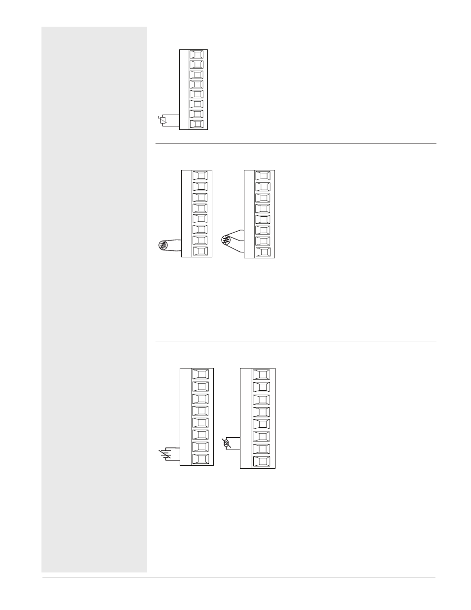
Input 1, 2, 3, 4 Thermistor
RMC Part # Digits 4, 6, 8, 10
S_
R_
Slot A, B, D, E
• >20 MΩ input impedance
Input 1: RMC(2,4,6)xxxxxxxxxxx
Input 2: RMCxx(2,6)xxxxxxxxx
Input 3: RMCxxxx(2,6)xxxxxxx
Input 4: RMCxxxxxx(2,6)xxxxx
Input 1, 2, 3, 4 RTD
RMC Part # Digits 4, 6, 8, 10
2-wire
RTD
S_
R_
Slot A, B, D, E
S3
S1
3-wire
RTD
T_
S_
R_
Slot A, B, D, E
S2
S3
S1
• platinum, 100 and 1,000 Ω @ 0°C
• calibration to DIN curve (0.00385 Ω/Ω/°C)
• 20 Ω total lead resistance
• RTD excitation current of 0.09 mA typical.
Each ohm of lead resistance may affect the
reading by 0.03°C for 100 Ω.
• For 3-wire RTDs, the S1 lead (usually
white) must be connected to R terminal
• For best accuracy use a 3-wire RTD to com-
pensate for lead-length resistance. All three
lead wires must have the same resistance.
Input 1: RMC(1,3,5)xxxxxxxxxxx
(S1,R1),(T1-S1-R1)
Input 2: RMCxx(1,5)xxxxxxxxx
(S2,R2),(T2-S2-R2)
Input 3: RMCxxxx(1,5)xxxxxxx
(S3,R3),(T3-S3-R3)
Input 4: RMCxxxxxx(1,5)xxxxx
(S4,R4),(T4-S4-R4)
Input 1, 2, 3, 4 Process
RMC Part # Digits 4, 6, 8, 10
-
+
S_
R_
volts
Slot A, B, D, E
-
+
T_
S_
amperes
Slot A, B, D, E
• 0 to 20 mA @ 100 Ω input impedance
• 0 to 10V
Î
(dc) @ 20 kΩ input impedance
• 0 to 50 mV
Î
(dc) @ 20 MΩ input impedance
• scalable
Input 1: RMC(1,3,5)xxxxxxxxxxx
(S1-/R1+),(T1+/S1-)
Input 2: RMCxx(1,5)xxxxxxxxx
(S2-/R2+),(T2+/S2-)
Input 3: RMCxxxx(1,5)xxxxxxx
(S3-/R3+),(T3-S3-R3)
Input 4: RMCxxxxxx(1,5)xxxxx
(S4-/R4+),(T4+/S4-)