Rm access rm control power supply plc, A conceptual view of rm hardware configurations – Watlow EZ-ZONE RMC User Manual
Page 12
Watlow EZ-ZONE
®
RMC Module
•
9
•
Chapter 1 Overview
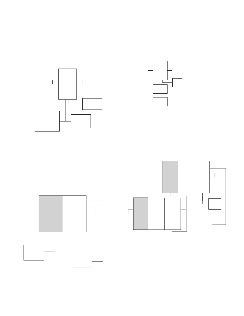
A Conceptual View of RM Hardware Configurations
Due to the scalability and flexibility in the RM sys-
tem a user has several options available in the way
that the hardware can be connected. Listed below
are a few examples.
RMC Module Connected to a Remote User In-
terface (RUI) and a PC
In this configuration the RUI and PC are connect-
ed to the RMC module via Watlow's Standard Bus
where both will be able to talk directly to the RMC
Slot C
PC
EZ-ZONE
Configurator
RUI
Power
Supply
RM
Control
module. The PC running EZ-ZONE Configurator
software and the RUI can be used to configure and
then monitor the RMC module.
RMC Module Connected to a Programmable
Logic Controller (PLC) on a DIN Rail
In this configuration the PLC can be connected to
the RMC module via the Access module using one or
more available protocols:
1. EtherNet/IP and or Modbus TCP
2. DeviceNet
3. Modbus RTU
Slot C
Slot C
Slot E
RM
Access
RM
Control
Power
Supply
PLC
RMC Module Connected to an Operator Inter-
face Terminal (OIT) through an RUI/Gateway
In this configuration the OIT can be running any of
a number of protocols communicating to the RM sys-
tem through Watlow's RUI/Gateway. Available proto-
cols for the RUI/Gateway follow:
1. EtherNet/IP and or Modbus TCP
2. DeviceNet
3. Modbus RTU
RM
Control
OIT
Power
Supply
Slot C
RUI
Gateway
RM System Connected to a Split Rail with OIT
In this configuration both the Inter-module Bus
(backplane communications) and Standard Bus are
connected between rails to allow for remote capabili-
ties. It is recommended that the split rail connection
not exceed 200 feet. In this configuration the OIT
can communicate with all modules (maximum 16
modules any combination with one Access module).
Slot E
Slot C
Slot C
Slot C
Slot C
Slot C
Slot C
OIT
Power
Supply
RM
Access
RM
Expansion
RM
Control
RM
Expansion
RM
Expansion
RM
Control