Outputs 1, 3, 5, 7 solid-state relay, form a, Outputs 2, 4, 6, 8 solid-state relay, form a, Watlow ez-zone – Watlow EZ-ZONE RMC User Manual
Page 33: Rmc module, Chapter 2 install and wire
Warning:
ç
Use National Electric (NEC) or other
country-specific standard wiring and
safety practices when wiring and
connecting this controller to a power
source and to electrical sensors or pe-
ripheral devices. Failure to do so may
result in damage to equipment and
property, and/or injury or loss of life.
Note:
Maximum wire size termination and
torque rating:
• 0.0507 to 3.30 mm2 (30 to 12 AWG)
single-wire termination or two 1.31
mm2 (16 AWG)
• 0.8 Nm (7.0 in-lb.) torque
Note:
Adjacent terminals may be labeled
differently, depending on the model
number.
Note:
To prevent damage to the controller,
do not connect wires to unused ter-
minals.
Note:
Maintain electrical isolation between
digital input-outputs, switched dc/open
collector outputs and process outputs
to prevent ground loops.
Note:
If the last two digits of the part number
are "12", this equipment is suitable for
use in CLASS I, DIVISION 2, Groups A,
B, C and D or Non-Hazardous locations
only. Temperature Code T4
Warning:
ç
Explosion Hazard – Substitution of
component may impair suitability for
CLASS I, DIVISION 2.
Warning:
ç
Explosion Hazard - Do not disconnect
while the circuit is live or unless the
area is known to be free of ignitable
concentrations of flammable sub-
stances.
Watlow EZ-ZONE
®
RMC Module
•
30
•
Chapter 2 Install and Wire
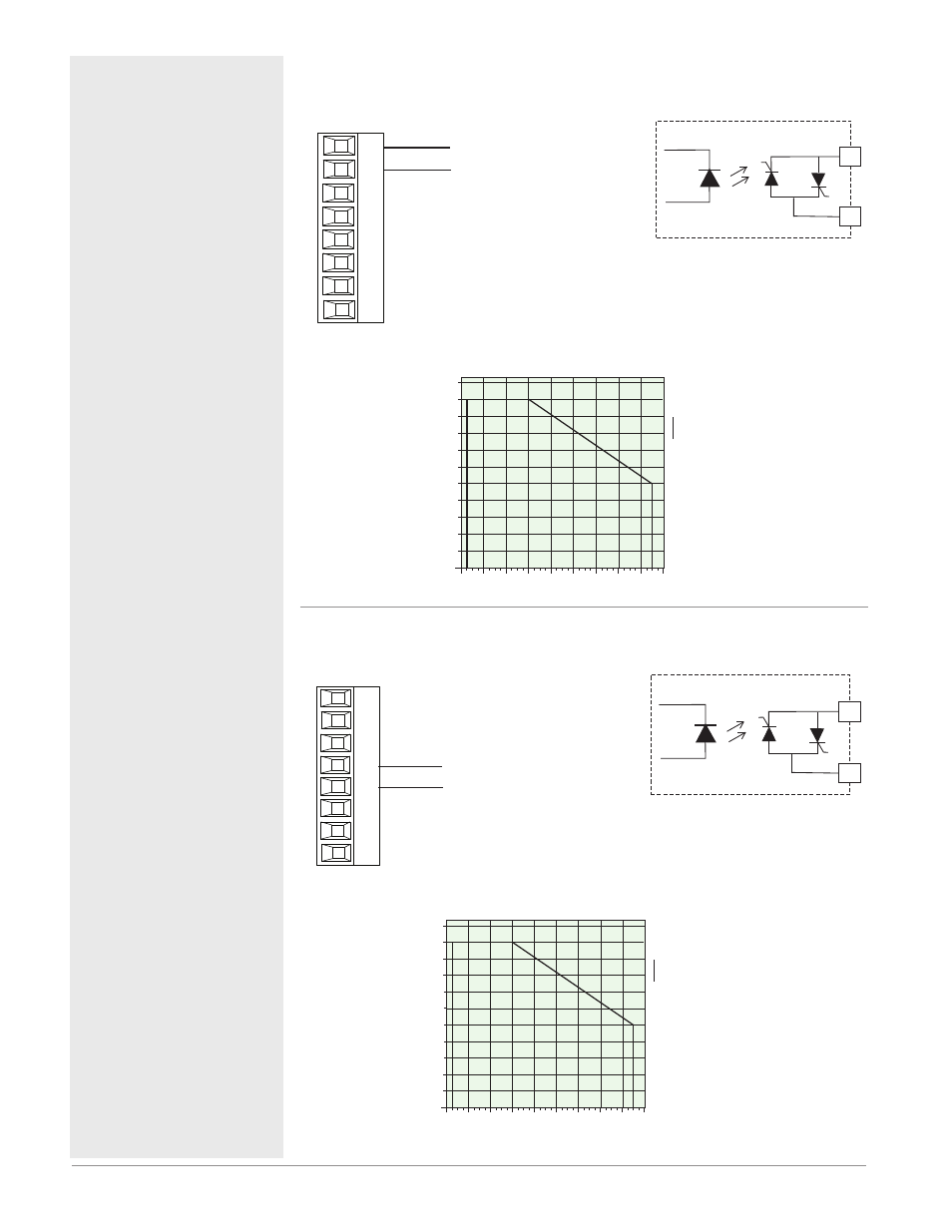
Outputs 1, 3, 5, 7 Solid-State Relay, Form A
RMC Part # Digit 5, 7, 9, 11 is G, M, S, T, Y or Z
normally open
common
L_
K_
Slot A, B, D, E
• 1 A at 20 to 264VÅ (ac)
maximum resistive load
• 20 VA 120/240VÅ (ac)
pilot duty
• Optical isolation, with-
out contact suppression
• maximum off state leak-
age of 105 microamperes
• Output does not supply
power.
• Do not use on dc loads.
• See Quencharc note.
K_
L_
1.1
0
-20
50
40
30
20
10
0
-10
60
70
A
mps RMS
Ambient Temperature (
o
C)
0.1
1
0.2
0.9
0.3
0.4
0.5
0.6
0.7
0.8
1 Amp SSR Derating Curve
Saf
e Oper
ating A
rea
Outputs 2, 4, 6, 8 Solid-State Relay, Form A
RMC Part # Digit 5, 7, 9, 11 is G, M, S, T, Y or Z
normally open
common
L_
K_
Slot A, B, D, E
• 1 A at 20 to 264VÅ (ac)
maximum resistive load
• 20 VA 120/240VÅ (ac)
pilot duty
• Optical isolation, with-
out contact suppression
• maximum off state leak-
age of 105 microamperes
• Output does not supply
power.
• Do not use on dc loads.
• See Quencharc note.
L_
K_
1.1
0
-20
50
40
30
20
10
0
-10
60
70
A
mps RMS
Ambient Temperature (
o
C)
0.1
1
0.2
0.9
0.3
0.4
0.5
0.6
0.7
0.8
1 Amp SSR Derating Curve
Saf
e Oper
ating A
rea