2 overview of g commands in the contour section, G commands for turning contours – HEIDENHAIN SW 548328-05 DIN Programming User Manual
Page 579
HEIDENHAIN MANUALplus 620, CNC PILOT 620/640
579
1
0
.2 Ov
erview of G commands in the CONT
OUR section
10.2 Overview of G commands in
the CONTOUR section
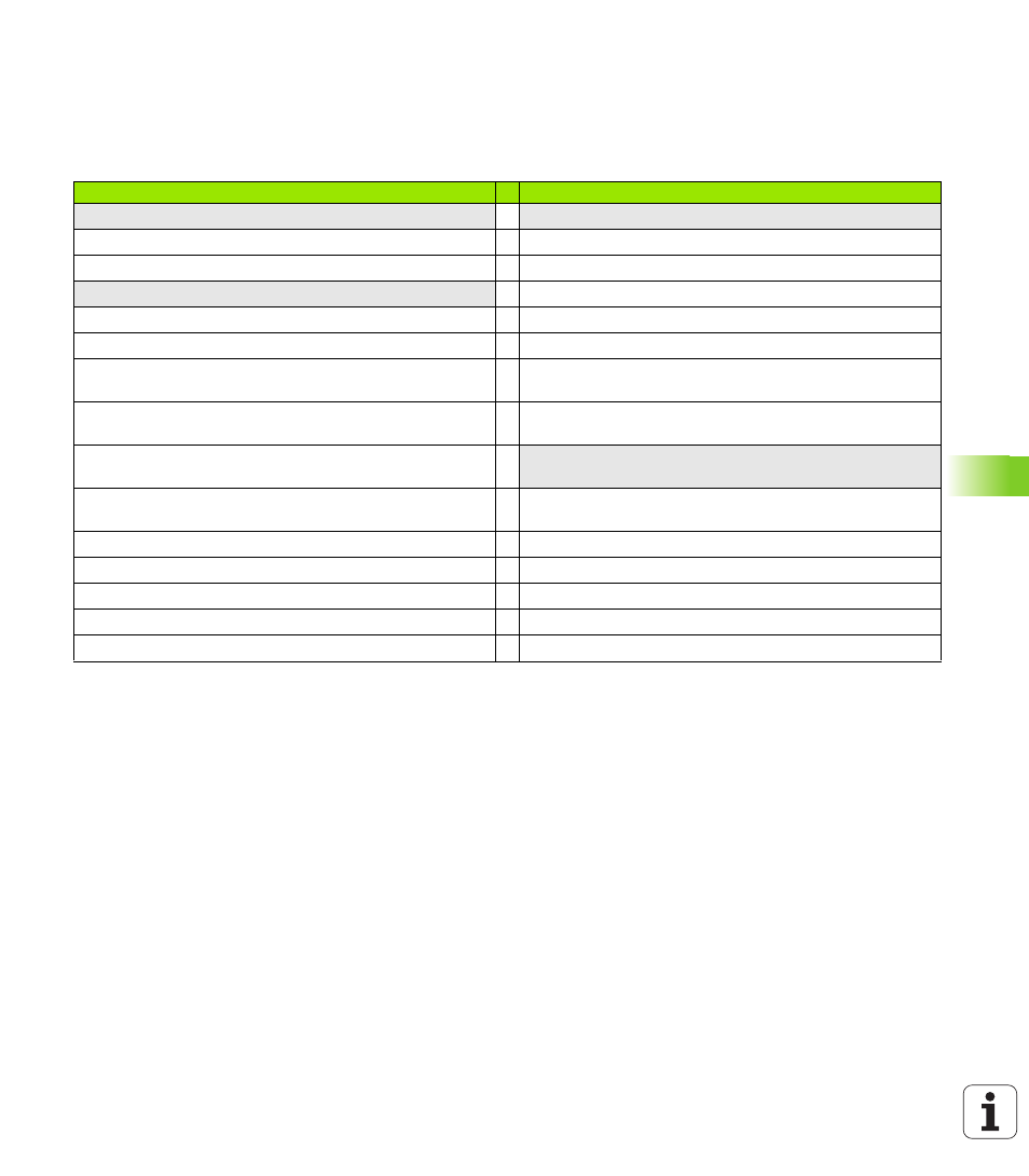
G commands for turning contours
Turning contour
Turning contour
Workpiece-blank definition
Contour form elements
G20-Geo
Chuck part, cylinder/tube
G22-Geo
Recess (standard)
G21-Geo
Cast part
G23-Geo
Recess/relief turn
Basic contour elements
G24-Geo
Thread with undercut
G0-Geo
Starting point of contour
G25-Geo
Undercut contour
G1-Geo
Line segment
G34-Geo
Thread (standard)
G2-Geo
Circular arc cw with incremental
center dimensioning
G37-Geo
Thread (general)
G3-Geo
Circular arc ccw with incremental
center dimensioning
G49-Geo
Bore hole at turning center
G12-Geo
Circular arc cw with absolute center
dimensioning
Help commands for contour definition
G13-Geo
Circular arc ccw with absolute
center dimensioning
Overview: Attributes for contour description
G38-Geo
Feed rate reduction
G44
Separation point
G52-Geo
Oversize
G95-Geo
Feed per revolution
G149-Geo Additive compensation