Circular slot pattern, lateral surface" unit, 1 0 units—milling, lat e ra l surf ace – HEIDENHAIN SW 548328-05 DIN Programming User Manual
Page 144
144
smart.Turn units
2.1
0
Units—Milling, lat
e
ra
l surf
ace
"Circular slot pattern, lateral surface" unit
The unit machines a circular slot pattern in which the individual
features are arranged at a regular spacing on the lateral surface. The
starting points of the slots correspond to the pattern positions. You
define the length and the position of the slots in the unit. The slot
width equals the diameter of the milling cutter.
Unit name: G792_Cir_Mant_C / Cycle: G792 (see page 340)
Access to the technology database:
Machining operation: Milling
Affected parameters: F, S, FZ, P
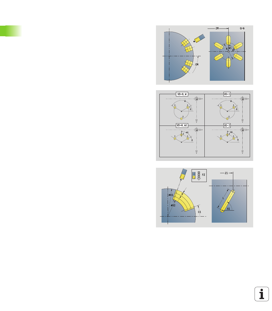
Pattern form
Q
Number of slots
ZM, CM Center point of pattern
A
Starting angle
Wi
Angle increment
K
Pattern diameter
W
End angle
V
Rotation direction (default: 0)
VD=0, without W: Figures are arranged on a full circle
VD=0, with W: Figures are arranged on the longer
circular arc
VD=0, with Wi: The algebraic sign of Wi defines the
direction (Wi<0: clockwise)
VD=1, with W: Clockwise
VD=1, with Wi: Clockwise (algebraic sign of Wi has no
effect)
VD=2, with W: Counterclockwise
VD=2, with Wi: Counterclockwise (algebraic sign of Wi
has no effect)
Cycle form
X1
Milling top edge (diameter value)
X2
Milling floor (diameter)
L
Slot length
A1
Angle to Z axis
P
Maximum infeed
FZ
Infeed rate
Further forms: