21 under c ut cy cles – HEIDENHAIN SW 548328-05 DIN Programming User Manual
Page 310
310
DIN programming
4.21 Under
c
ut cy
cles
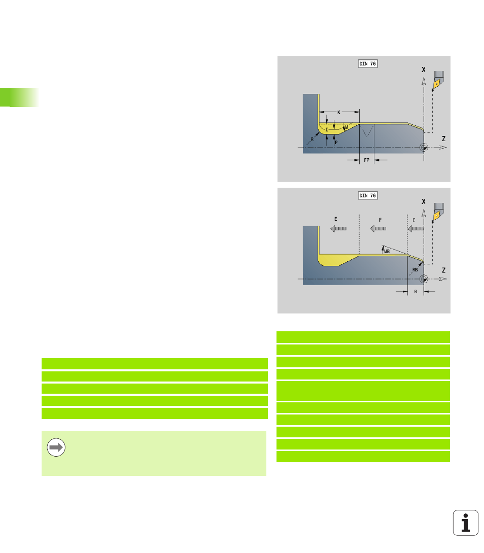
Undercut according to DIN 76 with cylinder
machining G853
G853 machines the adjoining cylinder, the undercut, and finishes with
the plane surface. It also machines a cylinder start chamfer when you
enter at least one of the parameters Cut-in length (1st cut length)
or Cut-in radius (1st cut radius).
Parameters that are not programmed are automatically calculated by
the Control from the standard table.
FP from the diameter
I, K, W, and R from FP (thread pitch)
Blocks following the cycle call
Example: G853
%853.nc
[G853]
N1 T2 G95 F0.23 G96 S248 M3
N2 G0 X60 Z2
N3 G853 FP1.5 I47 K15 W30 R2 P1 B5 RB2
WB30 E0.2 H1
N4 G0 X50 Z0
N5 G1 Z-30
N6 G1 X60
N7 G80
END
Parameters
FP
Thread pitch
I
Undercut depth (default: value from standard table)
K
Undercut length (default: value from standard table)
W
Undercut angle (default: value from standard table)
R
Undercut radius (default: value from standard table)
P
Oversize:
P is not defined: The undercut is machined in one pass
P is defined: Division into pre-turning and finish-turning
– P = longitudinal oversize; the transverse oversize is preset
to 0.1 mm
B
Cut-in length (1st cut length)—no input: No chamfer machined
at start of cylinder
RB
Cut-in radius (1st cut radius)—no input: 1st cut radius is not
machined
WB 1st cut angle (default: 45°)
E
Reduced feed for machining the undercut (default: active feed
rate)
H
Type of departure (default: 0):
0: Tool returns to the starting point
1: Tool remains at the end of the plane surface
N.. G853 FP.. I.. K.. W.. /Cycle call
N.. G0 X.. Z.. /Corner point of cylinder start chamfer
N.. G1 Z.. /Undercut corner
N.. G1 X.. /End point of plane surface
N.. G80 /End of contour definition
Undercuts can only be executed in orthogonal, paraxial
contour corners along the longitudinal axis.
Cutting radius compensation:
Active.
Oversizes:
are not taken into account.