Longitudinal roughing g810, 1 7 cont our -based t u rn ing cy cles – HEIDENHAIN SW 548328-05 DIN Programming User Manual
Page 264
264
DIN programming
4.1
7
Cont
our
-based t
u
rn
ing cy
cles
Longitudinal roughing G810
G810 machines the defined contour area. The reference to the
contour to be machined can be transferred in the cycle parameters, or
the contour can be defined directly after the cycle call (see "Working
with contour-based cycles" on page 262). The contour to be machined
can contain various valleys. If required, the area to be machined is
divided into several sections.
Parameters
ID
Auxiliary contour—ID number of the contour to be machined
NS
Starting block number (beginning of contour section)
NE
End block number (end of contour section)
NE not programmed: The contour element NS is machined
in the direction of contour definition.
NS=NE programmed: The contour element NS is machined
opposite to the direction of contour definition.
P
Maximum infeed
I
Oversize in X direction (diameter value) – (default: 0)
K
Oversize in Z direction (default: 0)
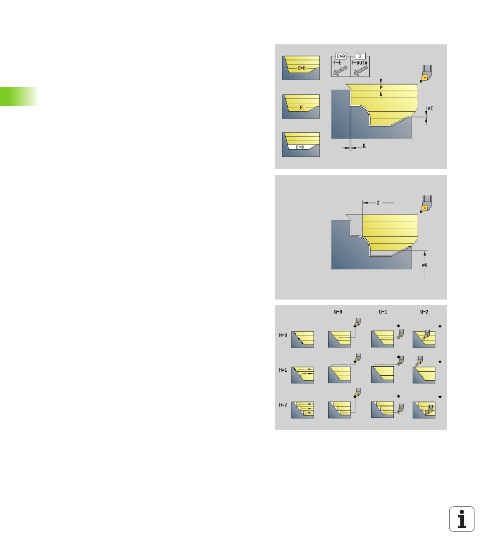
E
Plunging behavior
E=0: Descending contours are not machined
E>0: Plunging feed rate
One input: Feed rate reduction depending on the plunge
angle – maximum 50%
X
Cutting limit in X direction (diameter value) – (default: no
cutting limit)
Z
Cutting limit in Z direction (default: no cutting limit)
A
Approach angle (reference: Z-axis) – (default: 0°/180°, parallel
to Z-axis)
W
Departing angle (reference: Z-axis) – (default: 90°/270°;
perpendicular to Z-axis)
H
Type of departure (default: 0)
0: With each cut (machine contour outline after each pass)
1: With the last cut (retracts at 45°; contour smoothing after
last pass)
2: No smoothing (retracts at 45°; no contour smoothing)
Q
Type of retraction at cycle end (default: 0)
0: Returns to starting point, first X, then Z direction
1: Positions in front of the finished contour
2: Retracts to safety clearance and stops