Chucking equipment section, Turret section, Chucking equipment section turret section – HEIDENHAIN SW 548328-05 DIN Programming User Manual
Page 48
48
NC programming
1
.3 Pr
ogr
a
m section code
CHUCKING EQUIPMENT section
In the CHUCKING EQUIPMENT program section you describe how
the workpiece is clamped.
TURRET section
The TURRET program section defines the assignment of the tool
carrier. For every assigned turret pocket, the tool ID number is
entered. For multipoint tools, every cutting edge is entered in the
turret list.
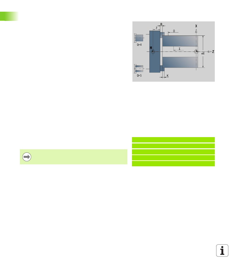
Parameters
H
No. of clamping (no. of chuck) (always program H=0)
D
Spindle number AWG
Z
Edge of chuck
B
Width of chuck
O
Cutting limitation, outside
I
Cutting limitation, inside
X
Clamping diameter of workpiece blank
K
Clamp length
Q
Chuck form
4: Externally clamped
5: Internally clamped
V
Shaft machining AWG
0: Chuck: Automatic separation points at largest and
smallest diameter
1: Shaft/chuck: Machining also starting from the chuck
2: Shaft/face driver: Outside contour can be machined
completely
Example: Turret table
. . .
TURRET
T1 ID"342-300.1"
T2 ID"C44003"
. . .
If you do not program the TURRET, the tools entered
in the tool list of the Machine operating mode will be
used.