1 y-axis contours— fundamentals, Position of milling contours, 1 y-axis contours—fundamentals – HEIDENHAIN SW 548328-05 DIN Programming User Manual
Page 478
478
DIN programming for the Y axis
6.1 Y
-axis cont
ours—F
undamentals
6.1
Y-axis contours—
Fundamentals
Position of milling contours
Define the reference plane or the reference diameter in the section
code. Specify the depth and position of a milling contour (pocket,
island) in the contour definition:
With depth P programmed in the previous G308 cycle.
Alternatively on figures: Cycle parameter depth P.
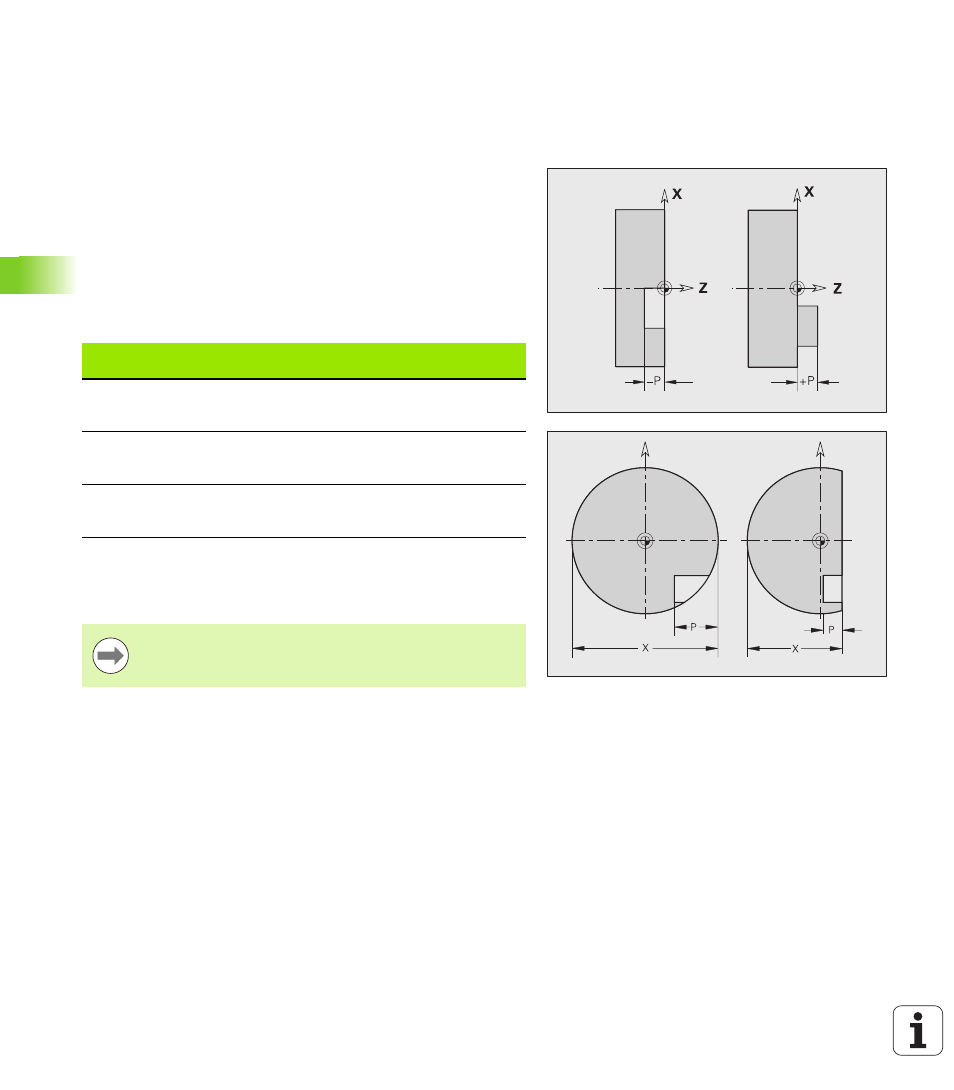
The algebraic sign of "P" defines the position of the milling contour:
P<0: Pocket
P>0: Island
X: Reference diameter from the section code
Z: Reference plane from the section code
P: Depth from G308 or from the figure definition
Position of milling contour
Section
P
Surface
Milling floor
FRONT
P<0
P>0
Z
Z+P
Z+P
Z
REAR SIDE
P<0
P>0
Z
Z–P
Z–P
Z
SURFACE
P<0
P>0
X
X+(P*2)
X+(P*2)
X
The area milling cycles mill the surface specified in the
contour definition. Islands within this surface are not
taken into consideration.