Linear pattern on lateral surface g411-geo, 8 lat er al surf ace cont ours – HEIDENHAIN SW 548328-05 DIN Programming User Manual
Page 239
HEIDENHAIN MANUALplus 620, CNC PILOT 620/640
239
4.8 Lat
er
al surf
ace cont
ours
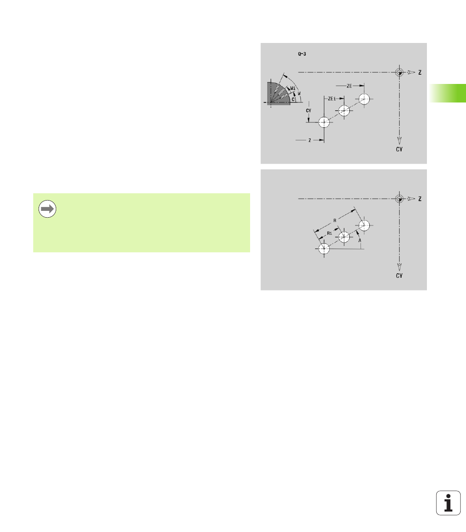
Linear pattern on lateral surface G411-Geo
G411 defines a linear hole or figure pattern on the lateral surface. G411
is effective for the hole/figure defined in the following block (G310 to
315, G317).
Parameters
Q
Number of figures (default: 1)
Z
Start point
C
Starting point (starting angle)
CY
Starting point as linear value; reference: unrolled reference
diameter
ZE
End point
ZEi Distance between figures in Z direction
W
End point (end angle)
Wi
Angular distance between figures
A
Angle to Z axis; (default: 0°)
R
Total length of pattern
Ri
Distance between figures (pattern distance)
If you program Q, Z and C, the holes/figures will be
ordered in a regular manner along the circumference.
Program the hole/figure in the following block without a
center.
The milling cycle calls the hole/figure in the following
block—not the pattern definition.