Linear slot on face g791, 26 milling cy cles – HEIDENHAIN SW 548328-05 DIN Programming User Manual
Page 339
HEIDENHAIN MANUALplus 620, CNC PILOT 620/640
339
4.26 Milling cy
cles
Linear slot on face G791
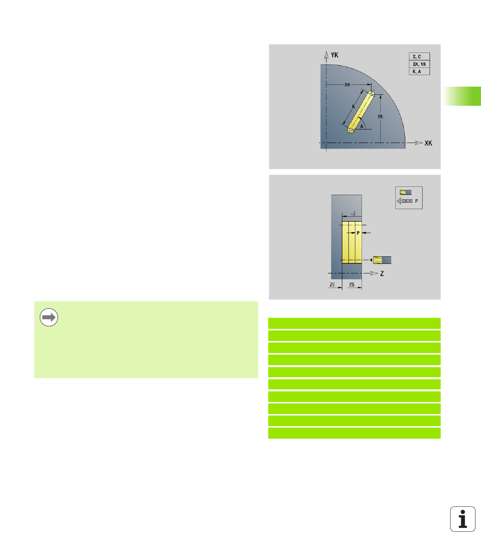
G791 mills a slot from the current tool position to the end point. The
slot width equals the diameter of the milling cutter. Oversizes are not
taken into account.
Parameter combinations
for definition of the end point: see help
graphic
Parameter combinations
for definition of the milling plane:
Milling floor ZE, milling top edge ZS
Milling floor ZE, milling depth J
Milling top edge ZS, milling depth J
Milling floor ZE
Example: G791
%791.nc
[G791]
N1 T7 G197 S1200 G195 F0.2 M104
N2 M14
N3 G110 C0
N4 G0 X100 Z2
N5 G100 XK20 YK5
N6 G791 XK30 YK5 ZE-5 J5 P2
N7 M15
END
Parameters
X
Final point of slot in polar coordinates (diameter)
C
Final angle. Final point of slot in polar coordinates (for angle
direction, see help graphic)
XK
Final point of slot (Cartesian)
YK
Final point of slot (Cartesian)
K
Slot length referenced to center of cutter
A
Slot angle (reference: see help graphic)
ZE
Milling floor
ZS
Milling top edge
J
Milling depth
J>0: Infeed direction –Z
J<0: Infeed direction +Z
P
Maximum approach (default: total depth in one infeed)
F
Approach feed (infeed rate) (default: active feed rate)
Rotate the spindle to the desired angle position before
calling G791.
If you use a spindle positioning device (no C axis), an
axial slot is machined centrically to the rotary axis.
If J or ZS is defined, the tool approaches to safety
clearance in Z and then mills the slot. If J and ZS are not
defined, the milling cycle starts from the current tool
position.