4 cont our f o rm elements – HEIDENHAIN SW 548328-05 DIN Programming User Manual
Page 207

HEIDENHAIN MANUALplus 620, CNC PILOT 620/640
207
4.4 Cont
our f
o
rm
elements
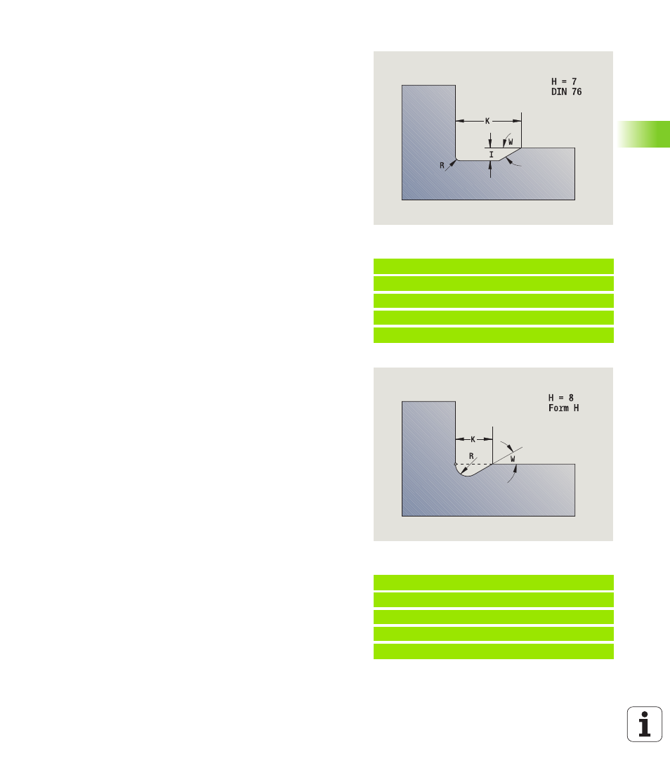
Undercut DIN 76 (H=7)
Program only FP. All the other values are automatically calculated from
the thread pitch in the standard table if they are not defined.
Undercut type H (H=8)
If you do not enter W, the angle will be calculated on the basis of K and
R. The end point of the undercut is then located at the "contour
corner."
Example: Call G25-Geo DIN 76
. . .
N.. G1 Z-15 [longitudinal element]
N.. G25 H7 FP2 [DIN 76]
N.. G1 X20 [transverse element]
. . .
Parameters
H
Undercut type DIN 76: H=7
I
Undercut depth (radius)
K
Width of undercut
R
Undercut radius in both corners of the undercut (default:
R=0.6*I)
W Undercut angle (default: 30°)
FP Thread pitch
BE, BF, BD, BP and BH (see "Machining attributes for form elements"
Example: Call G25-Geo type H
. . .
N.. G1 Z-15 [longitudinal element]
N.. G25 H8 K4 R1 W30 [type H]
N.. G1 X20 [transverse element]
. . .
Parameters
H
Undercut type H: H=8
K
Width of undercut
R
Undercut radius—no value: The circular element is not
machined
W Plunge angle—no value: W is calculated
BE, BF, BD, BP and BH (see "Machining attributes for form elements"
