Tilting the working plane g16, 4 w o rk ing plan es – HEIDENHAIN SW 548328-05 DIN Programming User Manual
Page 498
498
DIN programming for the Y axis
6.4 W
o
rk
ing
plan
es
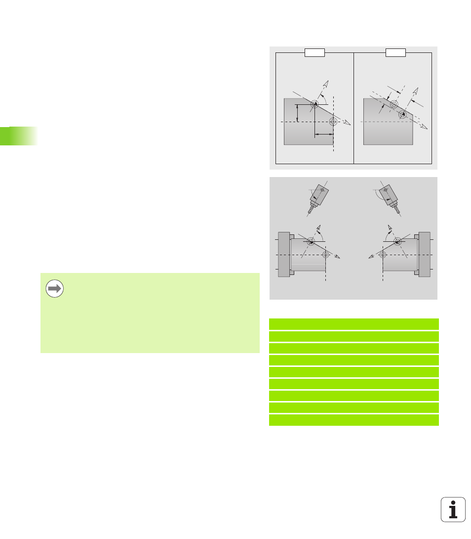
Tilting the working plane G16
G16 executes the following transformations and rotations:
Shifts the coordinate system to the position I, K
Rotates the coordinate system by the angle B; reference point: I, K
Shifts, if programmed, the coordinate system by U and W in the
rotated coordinate system
G16 Q0
resets the working plane. The zero point and coordinate
system defined before G16 are then in effect again.
G16 Q2
restores the previous G16 plane.
The positive Z axis is the reference axis for the "plane angle B." This
also applies to a mirrored coordinate system.
Example: "G16"
. . .
MACHINING
...
N.. G19
N.. G15 B130
N.. G16 B130 I59 K0 Q1
N.. G1 x.. Z.. Y..
N.. G16 Q0
. . .
X
U, W
B, I, K
K
I
Z
B
X
U
W
Z
Z
B
X
Z
B
X
Parameters
B
Plane angle; reference: positive Z axis
I
Plane reference in X direction (radius)
K
Plane reference in Z direction
U
Shift in X direction
W
Shift in Z direction
Q
Enable/disable tilting the working plane
0: Disable tilted working plane function
1: Tilt working plane
2: Restore previous G16 plane
Please note:
X is the infeed axis in a tilted coordinate system. X
coordinates are entered as diameter coordinates.
Mirroring the coordinate system has no effect on the
reference axis of the tilt angle ("B axis angle" of the tool
call).
Other zero point shifts are not permitted while G16 is
active.