Defining the basic contour, Defining form elements, Defining the basic contour defining form elements – HEIDENHAIN SW 548328-05 DIN Programming User Manual
Page 554: 5 example
554
TURN PLUS
7.
5 Example
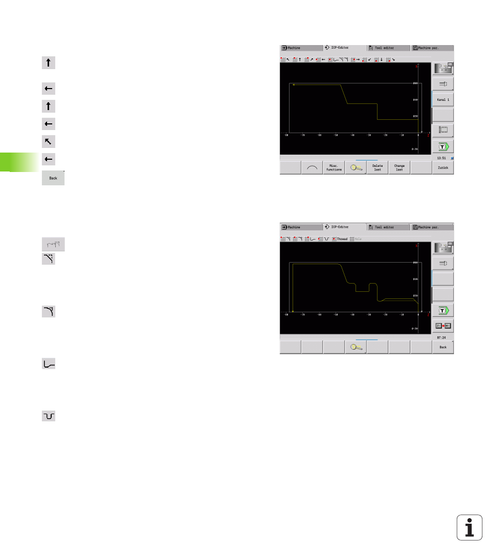
Defining the basic contour
Select "ICP > Finished part (> Contour)."
Enter start point of the contour X = 0; Z = 0 and end
point of the element X = 16
Enter Z = –25
Enter X = 35
Enter Z = –43
Enter X = 58; W = 70
Enter Z = –76
Press the "Back" soft key to go back one menu level.
Defining form elements
Chamfer at corner of threaded shank:
Select the form elements.
Select "Form > Chamfer."
Select the corner of the threaded shank.
"Chamfer" dialog box: Chamfer width = 3 mm
Rounding arcs:
Select "Form > Rounding."
Select the corners for the rounding arcs.
"Rounding" dialog box: Rounding radius = 2 mm
Undercut:
Select "Form > Undercut > Undercut type G."
Select the corner for the undercut.
"Undercut type DIN 76" dialog box
Recess:
Select "Form > Recess > Recess standard / G22."
Select the basic element for the recess.
"Recess standard / G22" dialog box:
Inside corner (Z) = 25 mm
Inside corner (Ki) = –8 mm
Recess diameter = 25 mm
Outside radius/chamfer (B) = –1 mm