Drive plc developer studio – Lenze DDS v2.3 User Manual
Page 31
Drive PLC Developer Studio
Program example
3-9
l
DDS EN 2.3
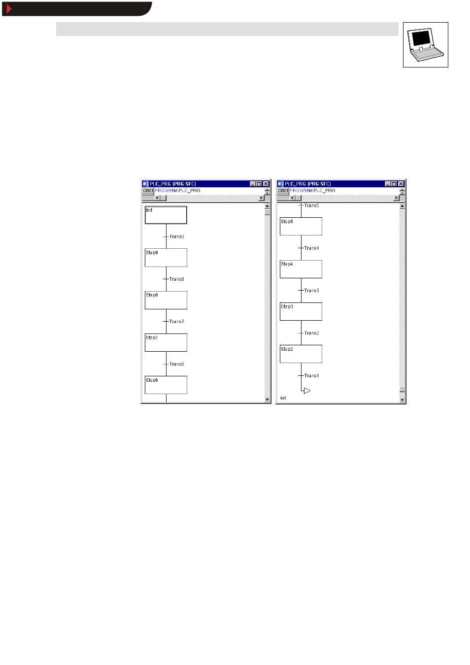
The traffic light example requires a step for every traffic light phase.
31.Select the transition Trans0 (click the horizontal line to the left of Trans0 ) to frame it with a
dotted line.
32.Select Insert
➞
➞
➞
➞Step transition (after) to insert a step transition after Trans0.
33.Repeat the above step seven times to create the following sequential function chart:
– To delete a step or transition, select the step and the associated transition, otherwise they
cannot be deleted.
– First click the step, press
•
Clicking the name of a transition or step directly will invert the text for editing.
34.Change the name of the first transition after Init to TRUE.
35.Change the names of all subsequent transitions to ” WAIT1.OK” .
•
The first transition switches all the time, all other transitions when WAIT1 in OK becomes
TRUE
, i.e. when the specified time has expired.
36.Change the names of the steps as described below (from top to bottom):
– Init (remains unchanged)
– CHANGE1
– GREEN1
– CHANGE2
– RED1
– CHANGE3
– GREEN2
– CHANGE4
– RED2
•
” CHANGEx” stands for a amber phase each time, “ GREEN1” means that traffic light 1 will be
green and “ GREEN2” applies for traffic light 2, “ RED1” means that traffic light 1 will be red
and “ RED2” applies for traffic light 2.
Show/Hide Bookmarks