Drive plc developer studio, Program example, 2 function block diagram – Lenze DDS v2.3 User Manual
Page 26
Drive PLC Developer Studio
Program example
3-4
l
DDS EN 2.3
The status of the variable STATE is used to switch the output variables for the associated light colour:
Traffic light phase
Input variable
Output variables
STATE
RED
AMBER
GREEN
OFF
Green
1
FALSE
FALSE
TRUE
FALSE
Amber
2
FALSE
TRUE
FALSE
FALSE
Red
3
TRUE
FALSE
FALSE
FALSE
Amber/red
4
TRUE
TRUE
FALSE
FALSE
Off
5
FALSE
FALSE
FALSE
TRUE
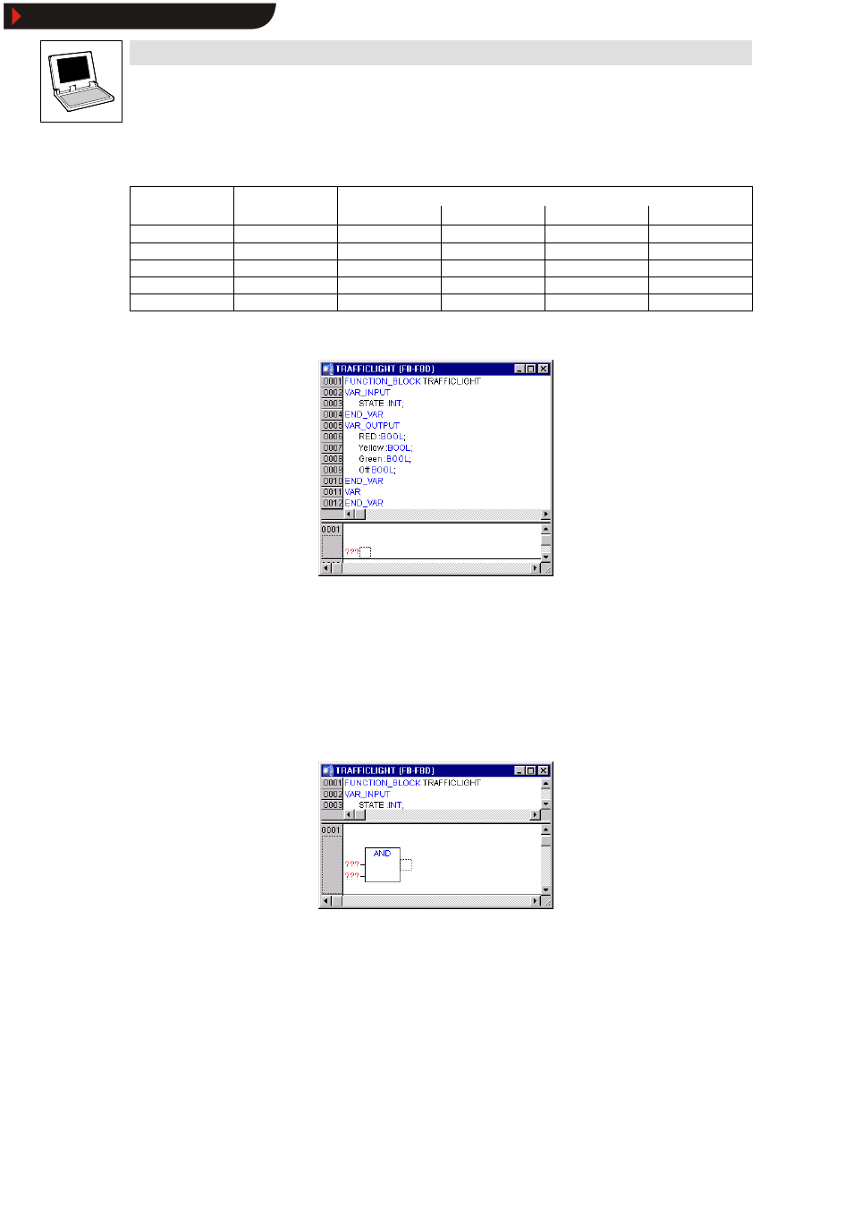
The declaration part of the function block TRAFFICLIGHT now looks as follows:
3.2.5.2
Function block diagram
Now use the input variable STATE of the organization unit to determine the values of the output
variables.
9. In the lower half of the editor window for the organization unit TRAFFICLIGHT, click the field
to the left of the first network (grey field with number 1) to select the network.
10.Select Insert
➞
➞
➞
➞Operator.
A box with the operator AND and two inputs is inserted in the first network:
11.Click “ AND” and change the text to “ EQ” .
12.Select the text “ ???” of the upper input and enter the variable STATE .
13.Select the three bottom question marks and name the input 1.
Show/Hide Bookmarks