7 the main program plc_prg, The main program plc_prg, Drive plc developer studio – Lenze DDS v2.3 User Manual
Page 30
Drive PLC Developer Studio
Program example
3-8
l
DDS EN 2.3
Process
The first interrogation establishes whether Q is already set to TRUE ( TRUE: timer running). [
Line 1]
•
If Q is TRUE, we will not change the assignment of DELAY but instead call function block
DELAY
without input (to check whether the time has already expired). [
Line 10]
•
If Q is FALSE, we will set the variable IN in DELAY to FALSE and thus at the same time ET
to 0 and Q to FALSE. [
Line 4]
All variables are now set to the desired initial status.
– Now save the time required from variable SETTIME in variable PT [
Line 5/6], and call DELAY
with IN:= TRUE. [
Line 7]
– In the function block DELAY , the variable ET will now be counted up until it reaches the
value SETTIME ; then Q will be switched to FALSE .
•
The negated value of Q will be saved after every WAIT cycle in OK [
Line 14/15]
•
As soon as Q becomes FALSE, OK becomes TRUE.
The timer is complete.
3.2.7
The main program PLC_PRG
The organization unit PLC_PRG is the main program for calling the two function blocks WAIT and
TRAFFICLIGHT .
29.To edit the organization unit PLC_PRG, activate its editor window by selecting
Object Organizer, tab Organization units and double-clicking PLC_PRG .
3.2.7.1
Declaration
To ensure that the function blocks created before can be used in PLC_PRG , it is necessary to declare
instances of these function blocks. The traffic light example requires two instances of the function
block TRAFFICLIGHT ( LIGHT1, LIGHT2) and one instance of the function block WAIT ( WAIT1).
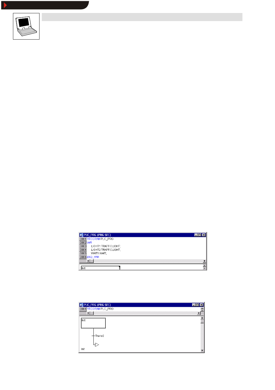
30.Use the declaration editor to declare as local variable (between the keywords VAR and
END_VAR
) the variables for the required instances.
3.2.7.2
Sequential function chart
The start-up diagram of an organization unit in SFC always consists of an action Init, a subsequent
transition Trans0 and a jump back to Init.
Show/Hide Bookmarks