Drive plc developer studio, Working with projects and objects – Lenze DDS v2.3 User Manual
Page 116
Drive PLC Developer Studio
Working with projects and objects
6-38
l
DDS EN 2.3
The following channels to the automation system are currently available for practical use:
•
Local gateway
•
Remote gateway
Via a TCP/IP network to a remote gateway PC with parallel port and dongle.
PC_lokal
PC_x
PC_Gateway
TCP/IP
/
‘local (shared memory)'
PC_PLC1
PC_PLC2
PC_PLC3
PC_PLC4
TPC/IP,
Pipe,
etc.
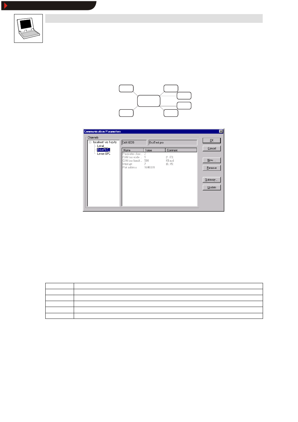
The dialog box
Communication parameters
is divided into four panes:
1. Channels
This is where the communication channels from the local host are displayed and those to be edited
are selected.
2. Communication driver display
The currently loaded communication driver (e. g. “CAN 8220 | JumpingLEDs.pro”).
3. Communication parameters
The parameters set for the currently loaded communication driver.
4. Buttons
OK
Quit and accept parameters
Cancel
Quit and reject parameters
New...
Create a new communication channel, via the parallel port/system bus dongle, for example
Remove
Remove a channel selected in pane
Channels
Gateway
Create a new communication channel to a remote gateway PC
Update
Check parameters or update the display
Creating a communication channel via the system bus dongle
The most commonly used communication option is via the system bus dongle connected to a local
PC via the parallel port.
Two parameters must be known to establish a connection to a certain automation system (e. g. 9300
Servo PLC) within a CAN bus network:
•
The device address on the bus (CAN bus node address). The device address is stored in code
C0350 of the automation system and must match the setting of the communication channel.
•
The baud rate set on the bus (CAN bus baud rate). The device address is stored in code
C0351 of the automation system and must match the setting of the communication channel.
Show/Hide Bookmarks