INFICON XTC/3 Thin Film Deposition Controller Operating Manual User Manual
Page 144
5 - 32
PN
07
4-
44
6-
P1
J
XTC/3 Operating Manual
14
(0x0e)
Xtal Fail
(Byte) 0 = good crystal / not in Xtal Fail;
1 = failed crystal / in Xtal Fail
15
(0x0f)
Max Power
(Byte) 0 = false not in max power;
1 = true in max power
16 (0x10)
Crystal Switching
(Byte) 0 = not switching; 1 = switching
17 (0x11)
End of process
(Byte) 0 = False; 1 = True
18 (0x12)
Stop
(Byte) 0 = False; 1 = True
19
(0x13)
Data Log
Returns data as follows
Layer # (Int)
Film # (Int)
Rate (Float) Å/Sec - One second average-
Thickness (Float) kÅ
Deposit time (Int) Seconds
Average power (Float) %
S Value (Int)
Q Value (Byte)
Begin Frequency (Float) HZ
End Frequency (Float) HZ
Crystal Life (Byte) %
Layer end type (Byte) -Normal end (0), Time power
end (1) or Stop (2) -
Cause of stop: (Byte)
0 = No stop
1 = Keyboard
5 = Crystal Fail
6 = Max Power
7 = Hand Controller
8 = Communications
9 = Digital Input
10 = Power Loss
11 = Rate Dev Error
12 = Crystal Switcher fail
20 (0x14)
Active Process
(Byte)
21 (0x15)
Power up error flag
(Byte) Bit is set indicating error as follows:
0 = Parameter loss on power cycle
1 = Process variables loss on power cycle
2 = Power down/up cycle
30
(0x1e)
Crystal Status
(2 Bytes) Each bit indicates one crystal of a multi-head
sensor. 1 = Good Crystal, 0 = Failed Crystal. LSB is
Crystal 1. All bits > number of crystals on sensor are 0.
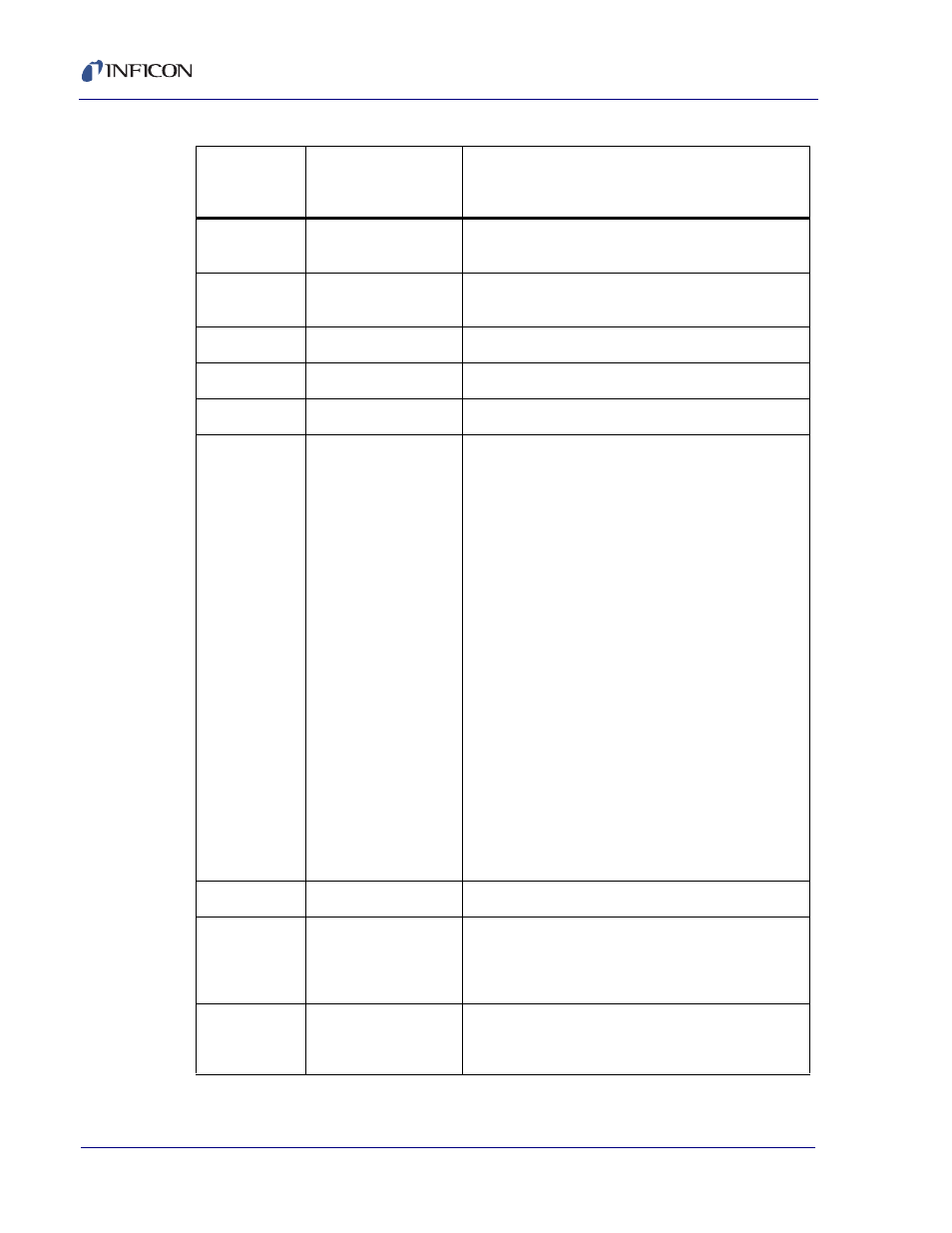
Table 5-4 Standard Status commands (continued)
S
(0x53)
Command ID
Description
Response:
Description (Data Format) Units -Detail-