INFICON XTC/3 Thin Film Deposition Controller Operating Manual User Manual
Page 143
5 - 31
PN
07
4-
44
6-
P1
J
XTC/3 Operating Manual
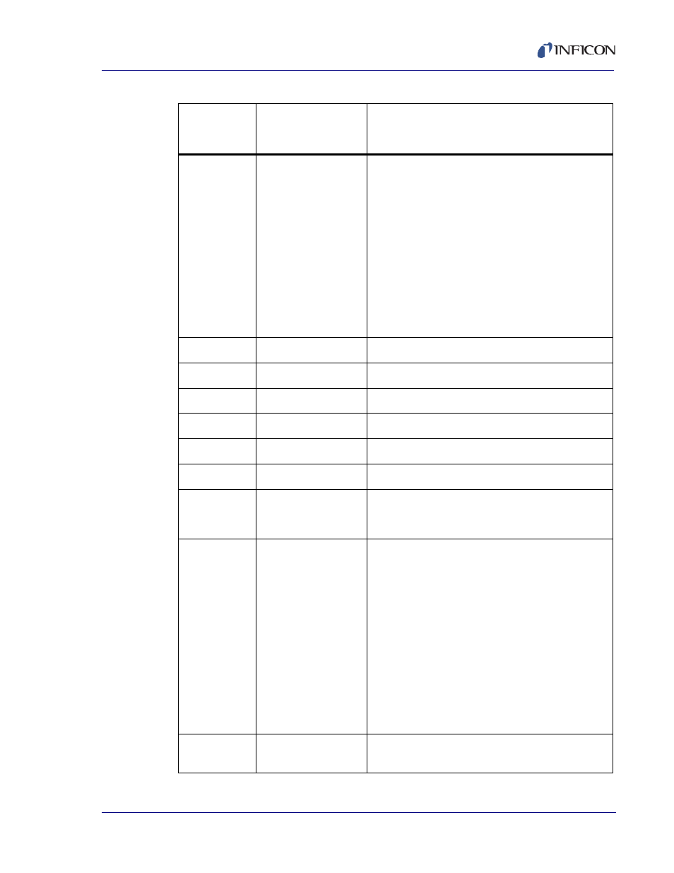
4
(0x04)
Current State
(Byte) - Decoded as follows: -
0 = Ready
1 = Crucible Switch
2 = Rise 1
3 = Soak 1
4 = Rise 2
5 = Soak 2
6 = Shutter Delay
7 = Deposit
8 = Rate Ramp
9 = Manual
10 = Time Power
11 = Idle Ramp
12 = Idle
5 (0x05)
Current State Time
(Int) - Number of seconds -
6 (0x06)
Active Layer
(Int)
7 (0x07)
Active Film
(Byte)
8 (0x08)
Active Sensor
(Byte) ( 1 or 2)
9 (0x09)
Crystal Life
(Byte)
10 (0x0a)
Power Source
(Byte) ( 1 or 2)
11
(0x0b)
Output Status Byte
(4 Byte) - Each bit represents an output -
(0 = not set, 1 = set)
Output 1 = LSB, Output 20 = 20th bit
12
(0x0c)
Input Status Byte
(2 Byte) - Each bit represents an input -
(0 = not set, 1 = set)
Input 1 = LSB, Input 9 = 9th bit
0x0100 = Input 1
0x0200 = Input 2
0x0400 = Input 3
0x0800 = Input 4
0x1000 = Input 5
0x2000 = Input 6
0x4000 = Input 7
0x8000 = Input 8
0x0001 = Input 9
0x0300 = Input 1 & 2
0x0101 = Input 1 & 9
0x3800 = Input 4, 5 & 6 etc
13
(0x0d)
Raw Frequency
(Int DDS units). - Multiply by 0.0034924596 to convert
to hertz.-
Table 5-4 Standard Status commands (continued)
S
(0x53)
Command ID
Description
Response:
Description (Data Format) Units -Detail-
- TGF10 Tracer Gas Filler (36 pages)
- Sensistor ILS500 F Leak Detection Filler (90 pages)
- T-Guard Leak Detection Sensor (85 pages)
- T-Guard Leak Detection Sensor Interface description (40 pages)
- Sensistor ISH2000P Hydrogen Leak Detector, Panel Model (51 pages)
- Sensistor ISH2000 HySpeed Hydrogen Leak Detector (54 pages)
- LDS3000 Modular Leak Detector (52 pages)
- LDS3000 Modular Leak Detector Interface description (56 pages)
- BM1000 Bus module (14 pages)
- I/O1000 I/O module (18 pages)
- CU1000 Control unit (24 pages)
- Helium Leak Detector Modul1000 (130 pages)
- Helium Leak Detector Modul1000 Interface description (40 pages)
- UL5000 Dry Helium Leak Detector (108 pages)
- UL5000 Dry Helium Leak Detector Interface description (14 pages)
- UL1000 Fab Dry Helium Leak Detector (119 pages)
- HLD6000 Refrigerant Leak Detector (76 pages)
- HLD6000 Refrigerant Leak Detector Interface Description (40 pages)
- IO1000 I/O module (18 pages)
- Ecotec E3000 Multigas-Sniffer-Leak Detector (92 pages)
- Ecotec E3000 Multigas-Sniffer-Leak Detector Interface description (36 pages)
- Sensistor XRS9012 Hydrogen Leak Detector User Manual (28 pages)
- Sensistor XRS9012 Hydrogen Leak Detector Maintenance manual (14 pages)
- Extrima Ex-certified Hydrogen Leak Detector (62 pages)
- Sensistor ILS500 Leak Detection System (107 pages)
- Sensistor ISH2000 Hydrogen Leak Detector (58 pages)
- Sensistor ISH2000 Hydrogen Leak Detector (108 pages)
- Sensistor Sentrac Hydrogen Leak Detector (86 pages)
- Protec P3000(XL) Helium Leak Detector (132 pages)
- Pilot Plus Vacuum Gauge (2 pages)
- CO Check Carbon Monoxide Meter (2 pages)
- GAS-Mate Combustible Gas Leak Detector (12 pages)
- Whisper Ultrasonic Leak Detector (8 pages)
- Vortex AC Refrigerant Recovery Machine 115V (20 pages)
- Vortex AC Refrigerant Recovery Machine 230V (16 pages)
- Wey-TEK Refrigerant Charging Scale & Optional Charging Module (2 pages)
- Wey-TEK Refrigerant Charging Scale & Optional Charging Module (44 pages)
- D-TEK CO2 Refrigerant Leak Detector (12 pages)
- TEK-Mate Refrigerant Leak Detector (12 pages)
- Compass Refrigerant Leak Detector (12 pages)
- D-TEK Select Refrigerant Leak Detector (12 pages)
- Explorer Portable Gas Chromatograph (369 pages)
- MicroFID II Portable Flame Ionization Detector (89 pages)
- DataFID Portable Flame Ionization Detector for Landfill Emissions Monitoring (91 pages)
- Hydrostik Hydrogen Fuel Cylinder Installation (7 pages)