IAI America XSEL-KX User Manual
Page 29
13
Part 1 Installation
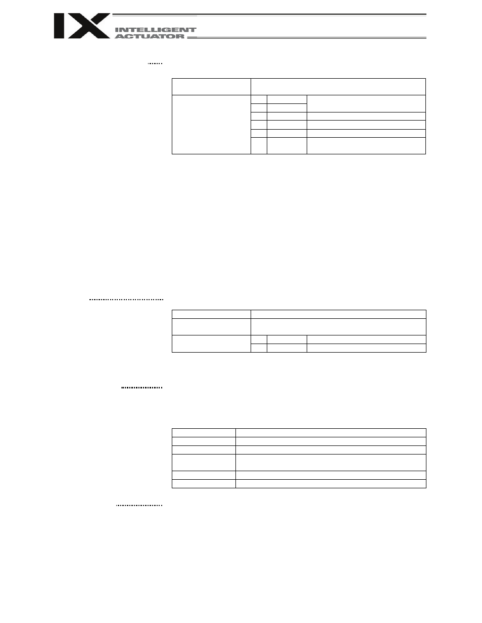
[8] System I/O connector
This connector is used to connect an emergency-stop switch, ENABLE
contact, ready relay, etc.
Connector
MC1.5/6-ST-3.5 by Phoenix Contact; 6-pin, 2-piece
connector
Terminal assignments
1 RDY OUT
Ready-status output contact
2 RDY OUT
3 ENB IN
Safety-gate input
4 +24V OUT +24-V power output for safety gate
5 EMG IN
Emergency-stop input
6 +24V OUT
+24-V power output for emergency
stop
Pins 1 and 2 form a contact-A output that turns ON under the following condition:
• SYSRDY is output (software = PIO trigger program can be run) and hardware is
normal (emergency stop is not being actuated and hardware error is not being
detected).
Pins 3 and 4 form a contact-B safety-gate input. Operation is enabled when the
pins are shorted, while the drive source is cut off when they are open.
Pins 5 and 6 form a contact-B emergency-stop input. Operation is enabled when
the pins are shorted, while an emergency stop is actuated when they are open.
Current flowing to the emergency stop contacts:
KX type (general-purpose type): 43 mA
± 10%
JX type (compact type):
30 mA
± 10%
The controller is shipped with pins 3 and 4, and 5 and 6, shorted by a cable,
respectively.
[9] I/O24V power connector
(general-purpose type
only)
This connector is used to externally supply I/O power to the insulated part
when DI and DOs are mounted in the I/O connectors explained in [14] and
[15] (2-pin, 2-piece connector by Phoenix Contact). 24 V must be supplied
externally.
Supported cable size
0.75 ~ 1.25 mm
2
(AWG16)
Connector
MC1.5/2-ST-3.5 by Phoenix Contact; 2-pin, 2-piece
connector
Terminal assignments
1 0V
I/O GND
2 24V IN
+24-V power input for I/Os
With a compact type, power is supplied externally to pin Nos. 1 and 50 of
the I/O connector in [14].
[10] Panel window
This window consists of a 4-digit, 7-segment LED display and five LED
lamps that indicate the status of the equipment.
For the information shown on the display, refer to 2, “Explanation of
Codes Displayed on the Panel Window” or the “Error Code Table.”
Meanings of Five LEDs
Name
Status when the LED is lit
RDY
CPU ready (program can be run)
ALM
CPU alarm (system-down level error), CPU hardware error
EMG
Emergency stop has been actuated, CPU hardware error,
power-system hardware error
PSE
Power-system hardware error
CLK
System clock error
[11] Mode switch
This alternate switch with lock is used to command a controller operation
mode. To operate the switch, pull it toward you and tilt.
Tilting the switch upward will select MANU (manual mode), while tilting it
downward will select AUTO (auto mode). Teaching can be performed only
in the MANU mode, but auto program start is not enabled in the MANU
mode.
(Refer to the types of manual operations explained on p.324.)