Installation environment, Heat radiation and installation, Chapter 3 – IAI America XSEL-KX User Manual
Page 20: Installation environment and noise measures
4
Part 1 Installation
Chapter 3 Installation Environment and Noise Measures
1. Installation Environment
(1) When installing and wiring the controller, do not block the ventilation holes provided for cooling.
(Insufficient ventilation will not only prevent the product from functioning fully, but it may also result in
failure.)
(2) Prevent foreign matter from entering the controller through the ventilation holes. Since the controller
is not designed as dustproof or waterproof (oilproof), avoid using it in a dusty place or place subject
to oil mist or splashed cutting fluid.
(3) Do not expose the controller to direct sunlight or radiant heat from a high heat source such as a heat-
treating furnace.
(4) Use the controller in a non-condensing environment free from corrosive or inflammable gases.
(5) Use the controller in an environment where it will not receive external vibration or impact.
(6) Prevent electrical noise from entering the controller or its cables.
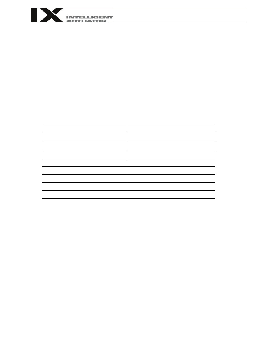
Environmental Condition of Controller
Item
Specification
Surrounding air temperature range
0
°C ~ 40°C
Forced air-cooling
24-VDC fan x 5 (compact type)
24-VDC fan x 6 (general-purpose type)
Surrounding humidity range
30% ~ 85%
Storage temperature range
-10
°C ~ 65°C
Dust protection structure
IP10
Power-source voltage
100 to 115/200 to 230 VAC, single-phase
Operating power-source voltage
±10%
Rated operating power-source frequency
50 Hz/60 Hz
2. Heat Radiation and Installation
Design the control panel size, controller layout and cooling method so that the ambient temperature
around the controller will be kept at or below 40°C.
Install the controller vertically on a wall, as illustrated below. The controller will be cooled by forced
ventilation (exhaust air will be discharged from the top). Be sure to install the controller in the
aforementioned direction and provide a minimum clearance of 150 mm above and 150 mm below the
controller.
If multiple controllers are to be installed side by side, providing additional suction fans on top of the
controllers will help maintain a uniform ambient temperature.
Provide a minimum clearance of 150 mm between the front side of the controller and a wall
(enclosure).