IAI America XSEL-KX User Manual
Page 27
11
Part 1 Installation
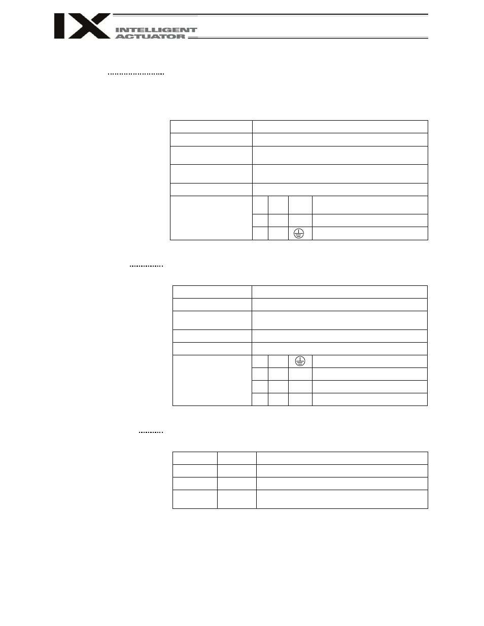
[4] External regenerative unit
connector
This connector is used to connect a regenerative resistance unit that may
be required when the controller is used in a high-speed/high-load
environment, etc., and the built-in regenerative resistance capacity is not
sufficient. Whether or not an external regenerative resistance is necessary
will be determined by the specific application such as axis configuration.
Overview of Fuse Holder Specifications
Item
Overview
Connector name
RB
Connector
GIC2.5/3-STF-7.62 by Phoenix Contact
3-pin, 2-piece connector
Cable size
1.0 mm
2
(AWG17 or equivalent), included in the
external regenerative box
Connected to
External regenerative box
Terminal
assignments
1 Out RB+
Regenerative resistance +
(Motor-driving DC voltage)
2
In
RB– Regenerative resistance –
[5] Motor connector
This connector is used to drive the motor inside the actuator.
Overview of Motor Connector Specifications
Item
Description
Connector name
M
Connector
GIC2.5/4-STF-7.62 by Phoenix Contact
4-pin, 2-piece connector
Cable
Dedicated motor cable
Connected to
Actuator
Terminal
assignments
1
PE (Protective grounding line)
2
Out
U
Motor-driving phase U
3
Out
V
Motor-driving phase V
4
Out
W
Motor-driving phase W
[6] Driver status LEDs
These LEDs monitor the operating status of the driver CPU that controls
the motor drive. The following three LEDs are provided.
Name
Color
Meaning when lit
ALM
Orange The driver is detecting an error.
SVON
Green
The servo is on and the motor is being driven.
BAT ALM
Orange
The voltage of the absolute-data backup
battery is low.