Toshiba Tosvert VF-AS1 User Manual
Page 236
E6581300
J-6
10
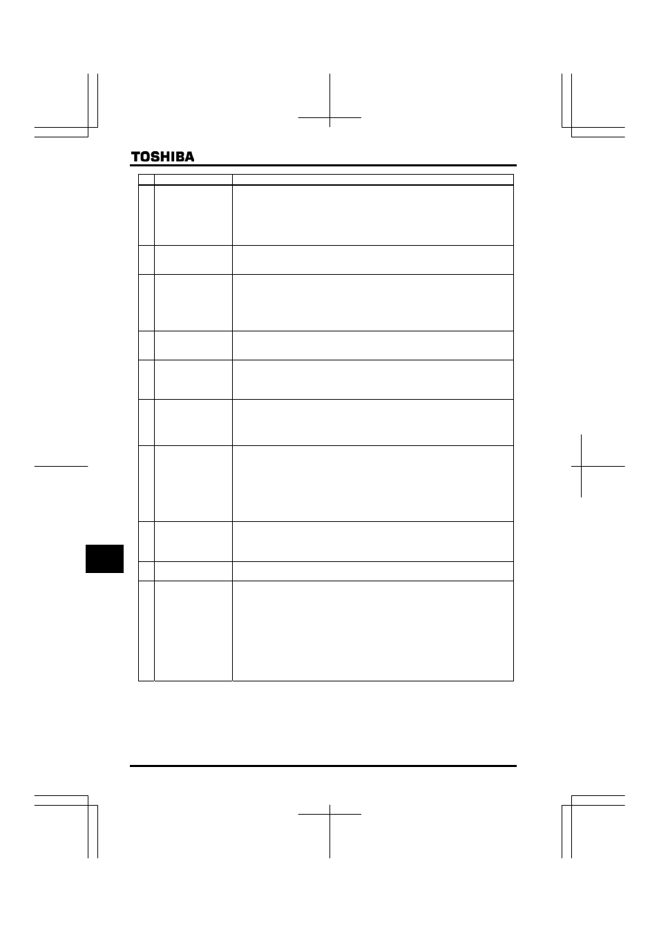
No.
Option name
Function, purpose.
(7)
Braking resistor
To be used to shorten deceleration time for the reason of frequently operated quick
deceleration and suspension or high inertia load. This increases consumption of regenerative
energy in dynamic braking.
• Braking resistor: (resistor + protective thermal relay) are built in.
• Braking unit (200kw or larger): dynamic brake drive circuit is built in.
A resistor needs to be prepared separately.
(8)
Motor noise reduction
filter (for large capacity
model only)
Can be used to suppress the magnetic noise from motor.
The magnetic noise will be approx. a few dB to 10dB(A) lower than the noise during operation
without reactor. (However, note that some magnetic noise occurs from the reactor.)
(9)
Motor end surge voltage
suppression filter
(for 400 V models only)
In a system in which 400 V class general motor is driven by a voltage PWM type inverter
using a high-speed switching device (IGBT, etc.), surge voltage depending on cable constant
may cause deterioration in insulation of motor winding. Take measures against surge voltage
such as use of insulation-reinforced motor, installation of AC reactor, surge voltage
suppression filter, sine wave filter and so on in the inverter’s output side.
Note) Set the carrier frequency to 2.2kHz when sine wave filter is used.
(10)
Control power supply
backup option
The VF-AS1 supplies control power from the main circuit power supply in it. The optional
backup unit is designed to supply control power in the event the main circuit power supply
shuts down.
(11)
LED Remote Keypad
option
(with parameter copy
function)
Extention operation panel unit with parameter copy function. Includes LED display,
RUN/STOP key, UP/DOWN key, MODE key, ENT key, EASY key, and COPY MODE key.
(When using this unit, set as follows: H (common serial transmission waiting time) =
(default setting). Use communication cable No. 14 to connect to the inverter.
(12)
LCD Remote Keypad
option
This LCD operation panel unit can be installed to the inverter unit. Includes LCD display, RUN
key, STOP/RESET key, job dial, ESC key, FWD/REV key and F1 to F4 key.
Special cable is needed to connect the inverter and LCD panel.
LCD cable type: CAB0071 (1m), CAB0073 (3m),
CAB0075 (5m)
(13)
RS485/USB
communication
converter unit
(for communication with
multiple inverters)
More than one inverter can be controlled with a personal computer and so on if this unit is
used for connection between inverters and personal computer.
• Computer link: Since this unit makes it possible to connect inverters with higher-class
computer, FA computer, etc., a data communication network can be
constructed among multiple inverters.
• Communication among inverters: For the purpose of proportional operation of multiple
inverters, a frequency data communication network can
be constructed among multiple inverters.
(14)
Communication cable
For RS485/USB communication (between inverter and RS485/USB communication
conversion unit)
Cable type: CAB0011 (1m), CAB0013 (3m),
CAB0015 (5m)
(15)
Remote control panel
A frequency meter, frequency setup device, RUN/STOP (forward, reverse) switch are built in
this operation panel. (Model: CBVR-7B1)
Applied control units of the AP series make various applied control possible if they are used in
combination with the inverter.
(16)
Application control units
■
Proportional control panel (APP-2B)
■
Ratio setup panel (APH-7B)
■
Regulated power supply board (APV-2B)
■
Cushion starter panel (APC-2B)
■
Synchronizing control panel
(APS-2B1)
■
Synchronizing transmitter (DRR-2)
■
Remote control panel (APM-2B)
■
Process control panel with built-in PI
controller (APJ-2B)
■
TG follower panel (APF-7B)
■
Current detection panel (APD-2B)
■
Torque control panel (APL-2B)
■
FV converter (APR-2B)
■
Loop controller (APU-2B)