5 display of alarm, pre-alarm, etc – Toshiba Tosvert VF-AS1 User Manual
Page 220
E6581301
H-12
8
8.5
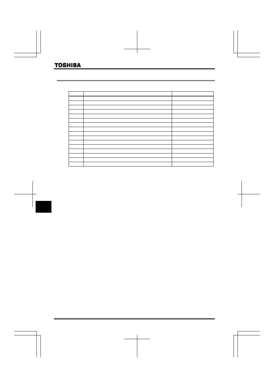
Display of alarm, pre-alarm, etc.
When the inverter alarm, pre-alarm, etc. occurred, the contents are displayed. (Some are not displayed.)
Listed below ones can be monitored via communication (FC91). Refer to 13.1 for the other alarms.
Bit
Description
Panel indication
0
Overcurrent pre-alarm
E
1
Inverter overload pre-alarm
N
2
Motor overload pre-alarm
N
3
Overheat pre-alarm
J
4
Overvoltage pre-alarm achieving PBR operation level
R
5
Main circuit undervoltage detected
OQHH
6
(Reservation area)
-
7
Low current alarm
-
8
Overtorque detection
-
9
Braking resistor overload pre-alarm
-
10
Cumulative operation time alarm
-
11
PROFIBUS/DeviceNet/CC-Link communication error
V
12
RS485 communication error
V
13
(Reservation area)
-
14
Forced deceleration stop because of a momentary power failure
UVQR
15
Pre-alarm stop because of prolonged lower-limit frequency operation
NUVR
Note: For each bit, “0” indicates normal condition and “1” indicates appearance of alarm, etc.
- Power Inverter (15 pages)
- 1800 (6 pages)
- TOSVERT VF-S11 (68 pages)
- Uninterruptible Power System G9000 (104 pages)
- Density (Consistency) Meter LQ500 (9 pages)
- MBSB80-225-43 (1 page)
- TOSNIC-7000S (53 pages)
- 1600EP Series (3 pages)
- 1500 (32 pages)
- TOSVERT VF-FS1 Series (16 pages)
- 4200FA XT1 (1 page)
- G3 Plus Pack (4 pages)
- Tosvert VF-A5 (149 pages)
- 1600 Series (3 pages)
- G9000 (100 pages)
- TEC EO1-33030 (54 pages)
- 1000 Series (2 pages)
- 1500 Plus (31 pages)
- G8000MM (6 pages)
- VT130G1 (99 pages)
- 4200FA Series (2 pages)
- VF-PS1 (10 pages)
- GX7 Series (6 pages)
- 4200FA XT (1 page)
- RMTI-EMD-HT (2 pages)
- W7 Series (6 pages)
- HX7 (6 pages)
- PDP002Z (18 pages)
- RELIABILITY IN MOTION 1700 (39 pages)
- 1700 Series (2 pages)
- G3 TOSVERT-130 (62 pages)
- B-852-TS12-QP (55 pages)
- 1000 (4 pages)
- E3 (7 pages)
- Adjustable Speed Drive H3 (122 pages)
- 55611-001 (2 pages)
- Black Gold Series (2 pages)
- Dura-Bull TX (6 pages)
- Current Relay RC803A-HP1 (19 pages)
- 1800 SERIES (2 pages)
- Isolated-Redundant UPS System (2 pages)
- RELIABILITY IN MOTION 1000 (54 pages)
- REMOTE-D (2 pages)
- 15-80KVA (2 pages)