Planning – Grass Valley Trinix NXT v.3.3.1 User Manual
Page 98
98
Trinix NXT — Installation and Service Manual
Section 2 — Planning Guide
Planning
The following section describes the Protected path planning process.
Note
The following discussion is based on a 1-based numbering scheme (Encore
Control system). If you are using a zero-based numbering system (Jupiter
AccuSwitch Control system), subtract 1 from all instances of input/output
numbers.
TRX-NXT-512x512
The recommended Protected path ranges for TRX-NXT-512x512 routers are
as follows:
For example, to protect an output in the range 1-128, choose a corre-
sponding input in the range 1-128; this will be the primary path. For the sec-
ondary (failover) path, choose an output in the range 257-384 and a
corresponding input in the range 257-384.
Alternatively, the high-range of connectors can be used for the primary
path and the low range for the secondary path, as shown in
Using either of these schemes will provide the most independent possible
paths through a TRX-NXT-512x512. In other words, the primary path will
use one set of input, matrix, and output boards connected to one power
source while the secondary path will use a different set of boards connected
to a different power source.
The maximum number of Protected paths for a TRX-NXT-512x512 router is
256.
A more detailed example is shown in
. This table shows a sequential
wiring scheme for a system yet to be installed or a system where cables will
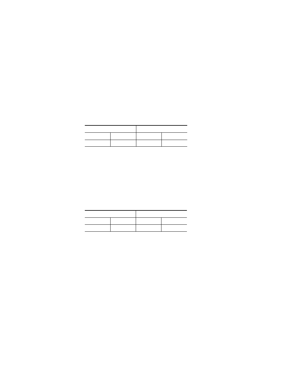
Table 3. Recommended Protected path Ranges
Primary Path
Secondary Path
Output
Input
Output
Input
1-256
1-256
257-512
257-512
Table 4. Alternative Protected Path Ranges
Primary Path
Secondary Path
Output
Input
Output
Input
257-384
257-384
1-128
1-128