Jupiter control, Jupiter – Grass Valley Trinix NXT v.3.3.1 User Manual
Page 214
214
Trinix NXT — Installation and Service Manual
Section 3 — Hardware Installation
Jupiter Control
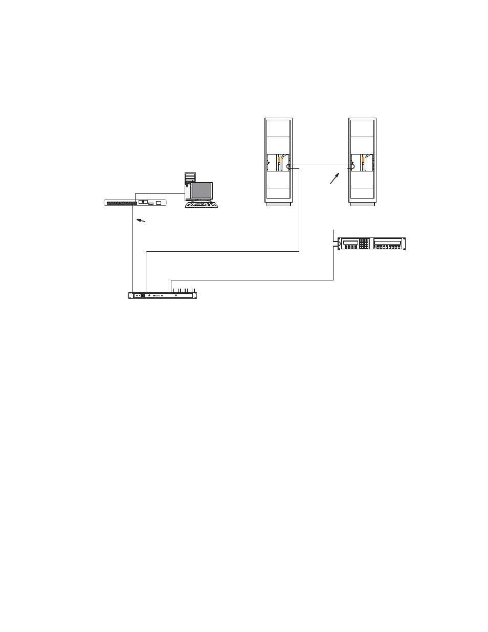
Figure 124. Control connections to Jupiter Facility Control System (example).
The Jupiter Facility Control system can be used to control the Trinix router
using a VM-3000 System Controller. The VM can receive switching com-
mands from a variety of serial sources, including Jupiter control panels or
an automation computer. The new CM-4000 System Controller is also avail-
able as a control interface.
In this application, the Trinix is operated in the external-Crosspoint bus
control mode, during which the Broadlinx board releases control of the
Crosspoint bus. Switch commands arriving at the Crosspoint bus connector
on the rear of the frame will be executed.
Follow these steps to use the Jupiter Facility Control System:
1.
Install the CC-2010 Matrix (Crosspoint bus) cable.
Interconnection from a Jupiter VM-3000 or CM-4000 control board is
via Crosspoint bus cable, which can be supplied in 3, 10, 25, or 50-foot
lengths. The Crosspoint bus (“XPT BUS”) connector (15-pin D-con-
CM-4000
System
Controller
MPK bus
Trinix routing
switcher(s)
Crosspoint bus
Jupiter control panels
T
Crosspoint bus
terminator
Jupiter file
server
10/100BaseT
LAN
Ethernet switch