Grass Valley Trinix NXT v.3.3.1 User Manual
Page 217
Trinix NXT — Installation and Service Manual
217
Jupiter Control
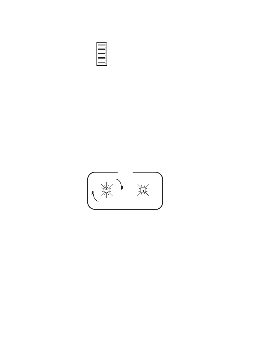
Figure 127. INT XPT CNTL” Rear-Panel DIP Switch
This will cause the Broadlinx board to release control of the Trinix
internal Crosspoint bus. Switch commands arriving at the Crosspoint
bus connector on the rear of the frame will be executed.
3.
Set Level switches:
Two back-panel rotary switches are used to set the level address of the
router.
For Jupiter control “Super” Crosspoint bus settings are used: the left-
hand switch is turned to the appropriate most significant bit on the
“Super” side of the switch. The least significant bit is set on the right
switch. For example, to set the Routing switcher level at “7” (the factory
default for serial digital video) the left switch would be set at “Super 0”
(straight up) and the right switch set to “7.” See
.
Figure 128.
Note
On all the rotary switches, use the triangular arrowhead for pointing (not the
screwdriver slot).
For synchronous switching on all outputs, the same sync signal must be
sent to the Jupiter and to the Trinix.
4.
Connect the LAN and Com Bus as required.
In most cases, the Trinix should be connected to the facility LAN to
allow system monitoring via the Broadlinx application. Com Bus con-
nections will be needed for Broadlinx monitoring of TRX-NXT-512x512
and multi-frame units.
5.
Refer to the Jupiter VM-3000 System Controller Installation and
Operation Manual or the Jupiter CM-4000 System Controller
Installation and Operation Manual for installation details about the
control system.
INPUT EXPAND
OUTPUT EXPAND
SYNC REDUNDANT
INT XPT CNTL
60Hz ENABLE
A
B
C
OPEN
CLOSED
0
1
2
3
4
5
6
7
8
9
10
11
12
13
14 15
64
0
16
32
48
80
96
112
0
16
32
48
64
80
96 112
LEVEL
SUPER
ULTRA