Trx-nxt-128x256 and trx-nxt-256x512 – Grass Valley Trinix NXT v.3.3.1 User Manual
Page 155
Trinix NXT — Installation and Service Manual
155
Power Supply Notes
TRX-NXT-128x256 and TRX-NXT-256x512
The 128x256 and 256x512Trinix Asymmetrical frames provide two DC input connec-
tors. The 512x1024 Asymmetrical frame has four DC connections A1 & B1 supply the
top half of the frame and A2 & B2 supply the bottom half. Each DC input is isolated
via power OR-ing diodes. For AC applications external power supplies modules are
used.
AC Applications
The back panel of the power supply frame provides a separate AC con-
nector for each power supply. Each power supply should be connected to
a separate 20A AC low line or 10A AC high line power circuit.
Note
Grass Valley strongly recommends, whenever possible, using the AC high
line to reduce line currents and heat within the power supplies.
Each power supply frame must be connected to the Trinix Asymmetrical
frame for power distribution and power supply status monitoring. For
more information, see 256X512 Default Power Supply Configurations
on
page 318
.
For the primary power distribution:
1.
Connect the DC power cable to the DC Input A connector on the back
of the main frame.
2.
Connect the power IFC cable to the PMBUS A connector on the back of
the main frame.
For the secondary power distribution:
1.
Connect the DC power cable to the DC Input B connector on the back
of the main frame.
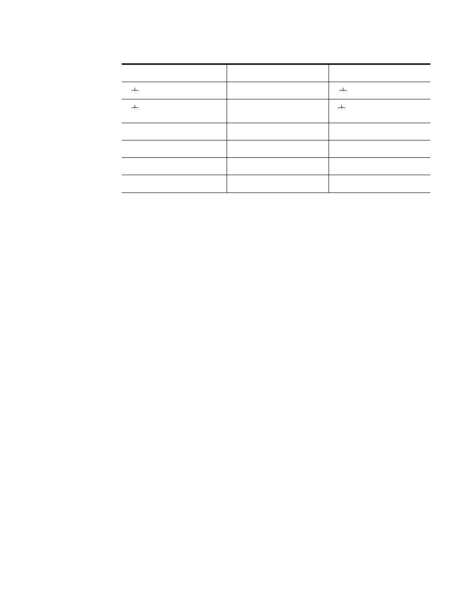
Power supply connector
Cable description
Main frame connector
(Ground)
Yellow/green
(Ground)
(Ground)
Plain black
(Ground)
DC Out + (left)
1 (red)
DC In + (left)
DC Out + (right)
2 (blue)
DC In + (right)
DC Out - (left)
3 (white)
DC In - (left)
DC Out - (right)
4 (yellow)
DC In - (right)