Switches s1-s4 (shown on, The trx-sr board leds – Grass Valley Trinix NXT v.3.3.1 User Manual
Page 177
Trinix NXT — Installation and Service Manual
177
NR/SR-33000 / SR-33500/ TRX-SR V-Phasing
Figure 91. TRX-SR DIP Switches
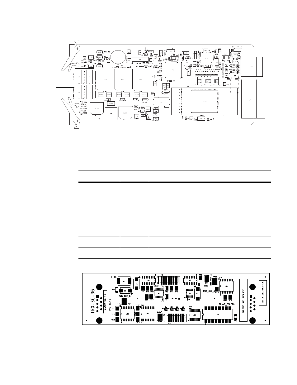
The TRX-SR Board LEDs
The TRX-SR uses the following LED colors for status (see
).
Table 34. TRX-SR Status LEDs
Figure 92. TRX-SC
LED
Color
Definition
MSTR ALARM
Red
A standard Trinix Board Alarm indicating that something is wrong on this board.
IN USE
Yellow
An output is being monitored by this module.
P2V1
Green
The +2.1V supply is OK.
P3V3
Green
The +3.3V supply is OK.
P5V
Green
The +5V supply is OK.
LOGIC VCC
Green
The ComBus Logic VCC is getting power from the backplane.
XC DONE
Green
The FPGA is configured
071827609_TRX-SR
DIP
Switches
S1-S4
This manual is related to the following products: